一、本地机房
去年进来公司时,才二十人,到现在发展到100号人。当时办公室还是蛮小,至多容纳40号人办公。到了7月份,公司计划就要搬迁办公室。鉴于当时办公环境,其实傻瓜交换机与路由,加上网线与电话线相互缠绕,跟一个蜘蛛网似的,掉线,也是常有发生。当超过40号人,去查看路由负裁,100%,能连上网,但掉包极为严重。鉴于,这种情况,建一个稳定的本地办公机房环境,就非常有必要了。
二、机器选型
| 序号 | 产品型号 | 描述 | 数量 |
| 路由器 | |||
| 1 | MSR2600-10-WiNet | H3C MSR 2600-10-WiNet路由器主机 | 1 |
| 上网行为管理 | |||
| 1 | NS-ACG1010+LIS-1 | H3C SecPath ACG1010 应用控制网关主机(12GE电口),含一年特征库升级 | 1 |
| 核心交换机 | |||
| 1 | LS-5500-24P-WiNet | H3C S5500-24P-WiNet 以太网交换机主机(24GE+4SFP Combo) | 1 |
| 接入POE交换机 | |||
| 1 | LS-5120-28P-POE-WiNet | H3C S5120-28P-POE-WiNet L2以太网交换机主机,24个10/100/1000BASE-T,4个SFP,支持AC110/220V,POE | 1 |
| 无线AC控制器 |
| 1 | EWP-WAC360 | 缺省管理16个AP,不可扩容,最大管理用户数512;1xWAN+4xLAN+2xUSB | 1 |
| 无线AP | |||
| 1 | EWP-WAP722-FIT | 内置天线,不可外接天线,2.4/5GHz双频866M,自带电源,胖瘦一体,吸顶面板式 | 9 |
| 网络机柜 | |||
| 1 | WD8632-A | 宽深高800*600*1600,标配 风扇4只,层板2块 1个电源排插,黑色 | 1 |
| 48口百兆接入交换 | |||
| 1 | LS-S3110-52TP-SI | H3C S3110-52TP-SI 以太网交换机主机(48FE+2GE+2SFP,交流供电) | 4 |
| 非屏蔽48口配线架 | |||
| 1 | 935548 | 索尔超五类非屏蔽48口配线架(满配) | 8 |
| 电话程控交换机 |
| 1 | WS824-9H | 8外线64分机 不可扩容 | 1 |
| 机房布线实施 | |||
| 1 | 机房布线 | 机房打线,捋线等工作,150信息点 |
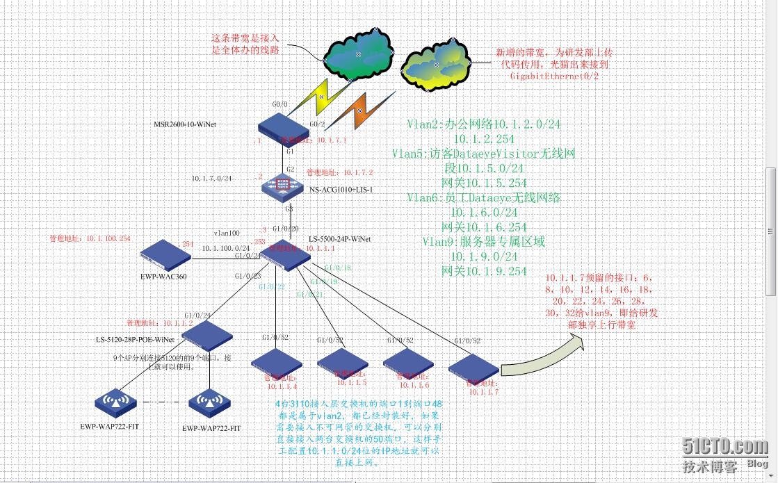
三、拓扑结构
四、配置步聚
-
路由器S2600-10
1.1 配置Telnet用户登录采用AAA认证方式
|
1
|
<H3C-S2600>system-view
|
开启Router的Telnet服务器功能。
|
1
|
telnet server
enable
|
配置Telnet用户登录采用AAA认证方式。
|
1
2
|
user-interface vty 0 4
authentication-mode scheme
|
设置Telnet用户和密码
|
1
2
3
4
5
|
local
-user admin
password cipher 填写密码
authorization-attribute level 3
service-
type
telnet terminal
service-
type
web
|
1.2 拨号1设置
|
1
2
3
4
5
6
7
8
9
10
11
|
interface Dialer1
nat outbound 3001
link-protocol ppp
ppp chap user 拨号账号
ppp chap password cipher 密码
ppp pap
local
-user 拨号账号 password cipher 密码
ip address ppp-negotiate
tcp mss 1024
dialer user 账号
dialer-group 1
dialer bundle 1
|
1.3 拨号2设置
|
1
2
3
4
5
6
7
8
9
10
11
|
interface Dialer2
nat outbound 3002
link-protocol ppp
ppp chap user 账号
ppp chap password cipher 密码
ppp pap
local
-user 账号 password cipher 密码
ip address ppp-negotiate
tcp mss 1024
dialer user 账号
dialer-group 2
dialer bundle 2
|
1.4配置ACL
|
1
2
3
4
|
acl number 3001
rule 0 permit ip
acl number 3002
rule 0 permit ip
source
10.1.9.0 0.0.0.255
|
1.5创建策略节点5,并应用到G0/2
|
1
2
3
4
|
policy-based-route server permit node 5
if
-match acl 3002
apply output-interface GigabitEthernet0
/2
policy-based-route server permit node 10
|
1.6 工作模式设置为三层模式(Rout),则作为一个三层以太网接口使用
G0/0接口
|
1
2
3
|
interface GigabitEthernet0
/0
port link-mode route
pppoe-client dial-bundle-number 1
|
G0/2接口
|
1
2
3
|
interface GigabitEthernet0
/2
port link-mode route
pppoe-client dial-bundle-number 2
|
1.7配置管理IP地址
|
1
2
3
4
5
|
interface GigabitEthernet0
/1
port link-mode route
ip address 10.1.7.1 255.255.255.0
tcp mss 1024
ip policy-based-route server
|
1.8设定静态路由
|
1
2
|
ip route-static 0.0.0.0 0.0.0.0 Dialer1
ip route-static 10.1.0.0 255.255.0.0 10.1.7.3
|
1.9 启启DHCP
|
1
|
dhcp
enable
|
1.10 设定触发拨号条件
|
1
2
|
dialer-rule 1 ip permit
dialer-rule 2 ip permit
|
这条命令用于设定触发拨号的条件,这条命令表示IP包可以
触发拨号。后面接口配置模式下的dialer-group命令与这条命令对应,用于指定该拨号接口
所使用的触发拨号条件。
1.11 查看接口详情
2.上网行为管理NS-ACG1010
没有做过多限制,仅用来查看当前网带带宽情况,这里以配置文件展示了,可以作参考
|
1
2
3
4
5
6
7
8
9
10
11
12
13
14
15
16
17
18
19
20
21
22
23
24
25
26
27
28
29
30
31
32
33
34
35
36
37
38
39
40
41
42
43
44
45
46
47
48
49
50
51
52
53
54
55
56
57
58
59
60
61
62
63
64
65
66
67
68
69
70
71
72
73
74
75
76
77
78
79
80
81
82
83
84
85
86
87
88
89
90
91
92
93
94
95
96
97
98
99
100
101
102
103
104
105
106
107
108
109
110
111
112
113
114
115
116
117
118
119
120
|
!config
authorized-table admin
authorized
read
all
authorized write all
!
user administrator admin
local
secret Hg6MAD7MGTUEcoT9gHG+LhDc6E07QwG71SmiEodL
/fQT/YirzsAURqDjk69469y
authorized-table admin
user administrator admin authorized-address first 0.0.0.0
/0
!
!
timezone 57
!
pki ca crl update-period 30
!
!
interface bvi2
ip address 10.1.7.2
/24
allow access https
allow access http
allow access
ping
allow access telnet
!
interface ge0
ip address 192.168.1.1
/24
allow access https
allow access http
allow access
ping
!
interface ge1
!
interface ge2
bridge-group 2
!
interface ge3
bridge-group 2
!
interface ge4
!
interface ge5
!
interface ge6
!
interface ge7
!
interface ge8
!
interface ge9
!
interface ge10
!
interface ge11
!
!address
!
!address6
!
!address-group
!
!service
!
!service-group
!
!schedule-day
!
!schedule-week
!
!schedule-month
!
!schedule-once
!
!user
!
!user-group
!
!
!user-policy
!
!
!
!
!
!
!
policy default-action permit
policy white-list
enable
!
snmp
community secret 6NSjZ2FJfHqUtCqRXdechDETsW7nP4FFcq1ujxx1HotuCZoZGsn14R7gwFVplw1
write-community secret QuVJ8MPv5S7noa5Lp+C7xY4UnIZD5gm5LCCvi9RLtC2fYqVZdaKQ0rdwLAIf36P
!
dhcp
!
!
!
ip route 0.0.0.0
/0
10.1.7.1
!
!user-param
!
user-param recognition threshold 60000
!user-webauth
!
!ip session limit
!
!
!
!
!
!
qos-profile line 01
limit ingress
maxbandwidth ingress 1000
match interface ge0
!
qos-profile channel def_01 parent 01
!
policy6 default-action permit
!
ha-config
!end
|
3.核心交换机LS-5500-24
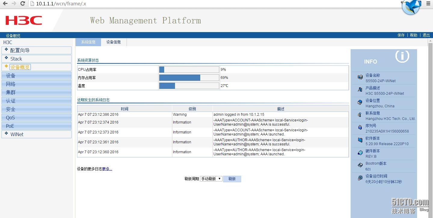
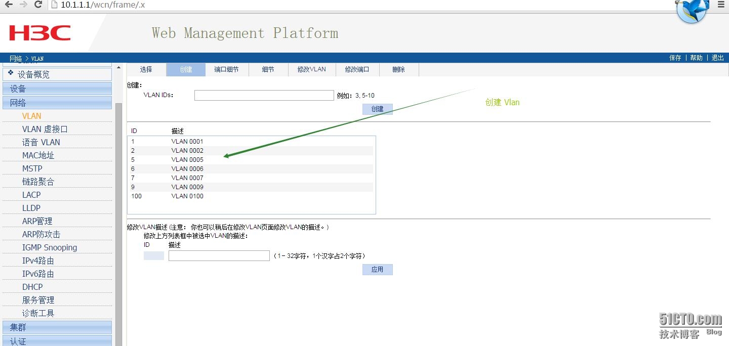
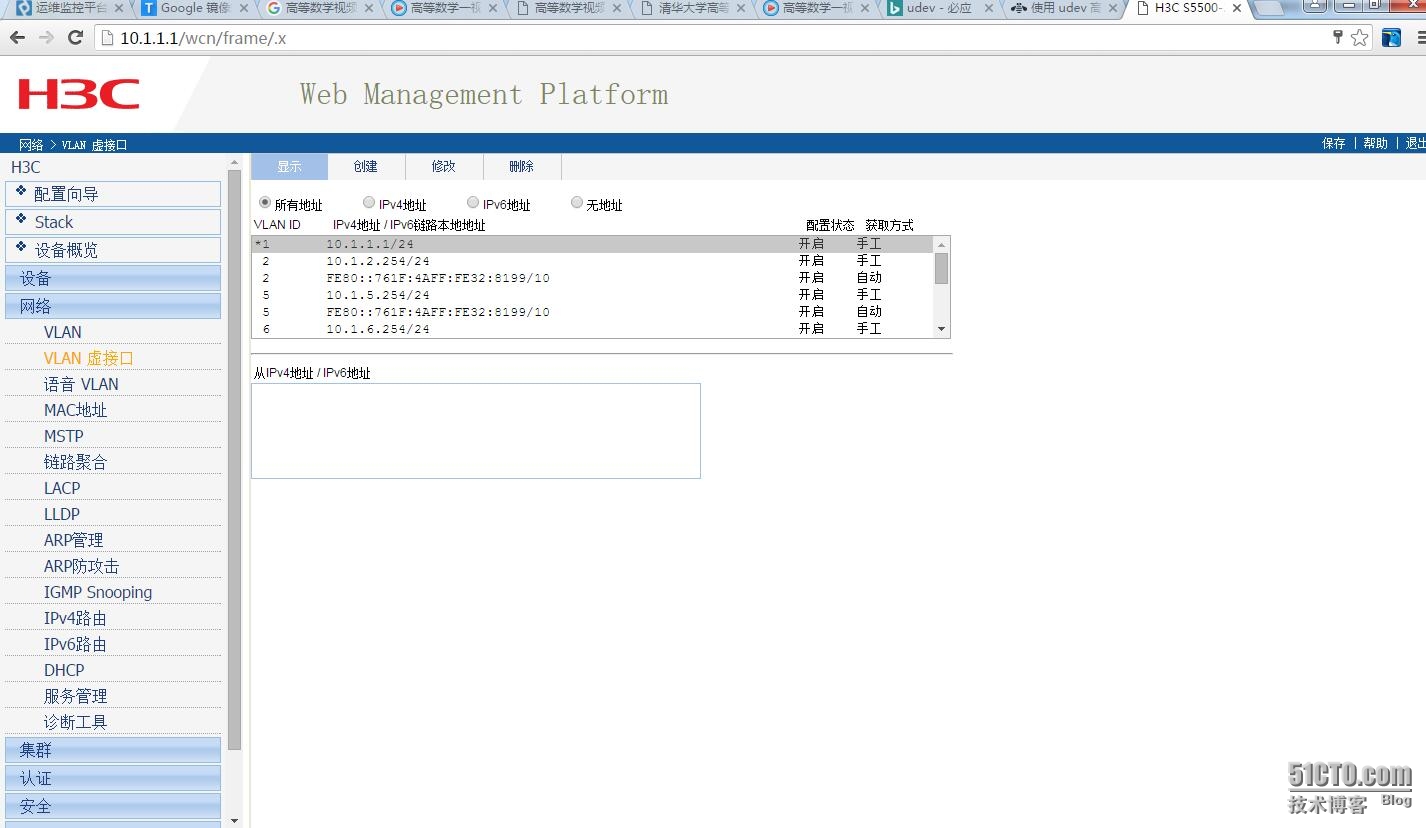
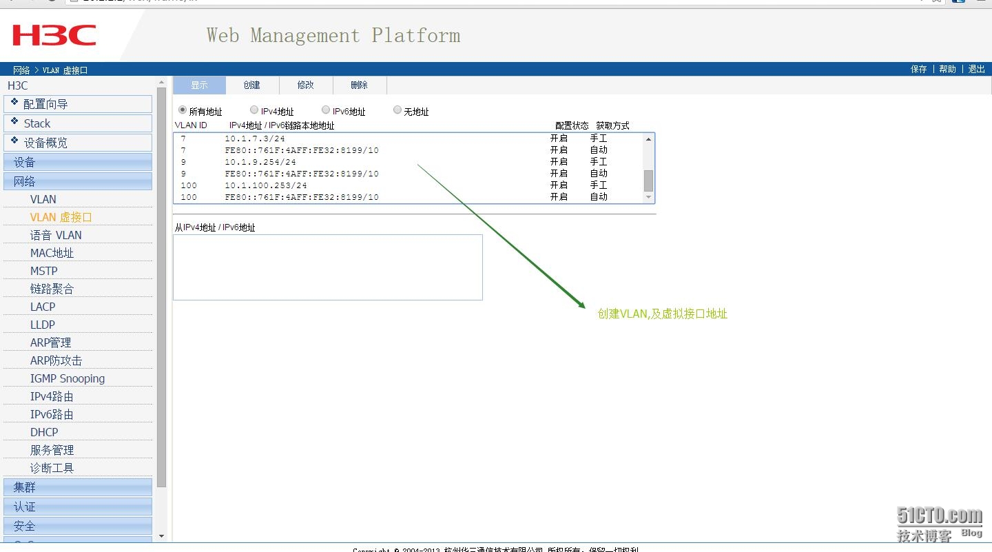
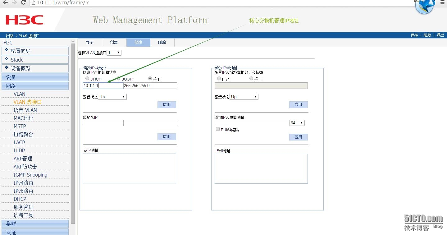
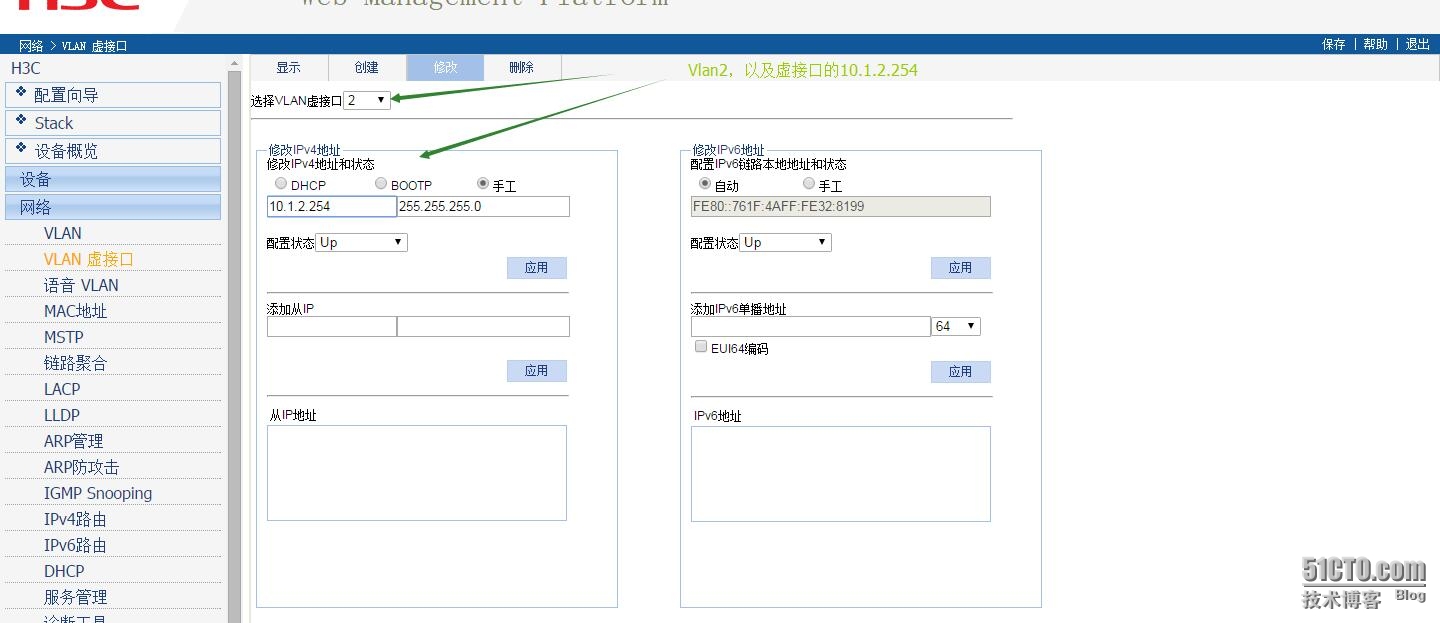
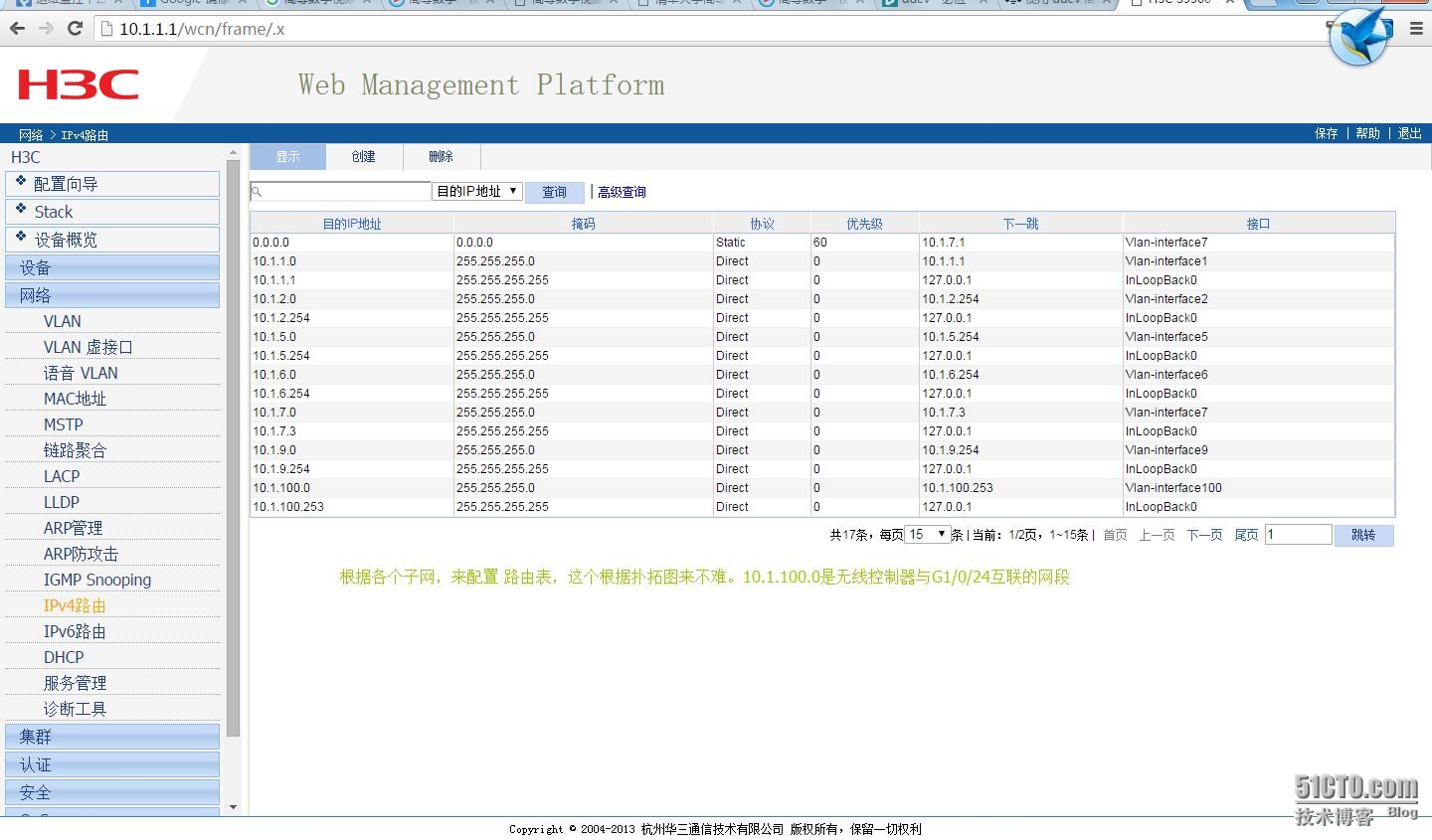
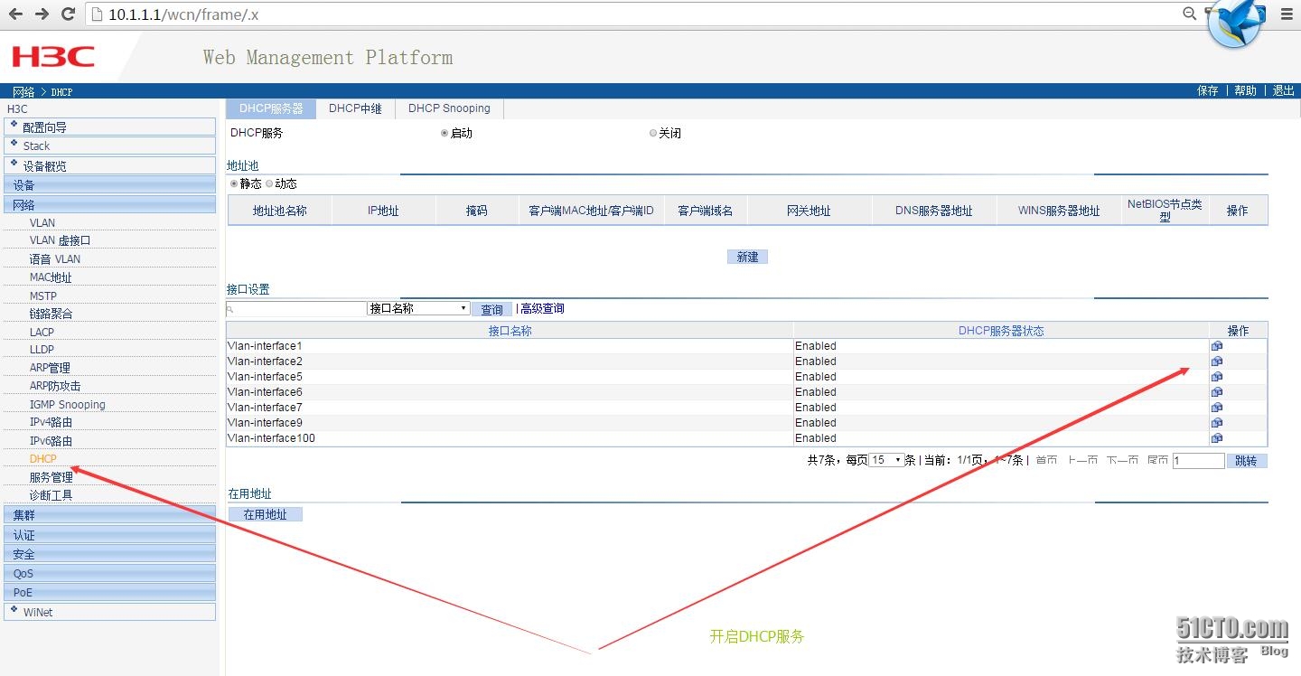
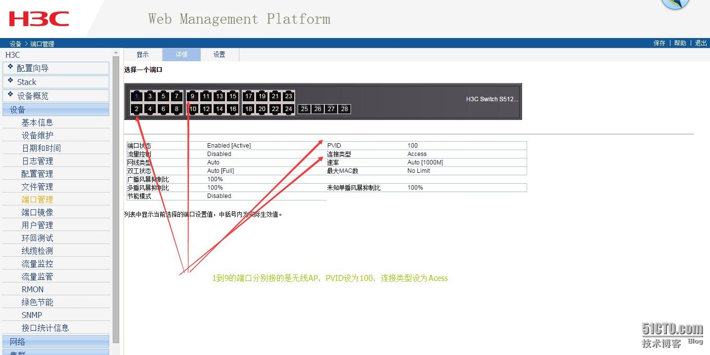
3.1 配置都在web界面,创建vlan1,vlan2,vlan5,vlan6,vlan7,vlan9,vlan100
3.2配置路由,以及开启DHCP
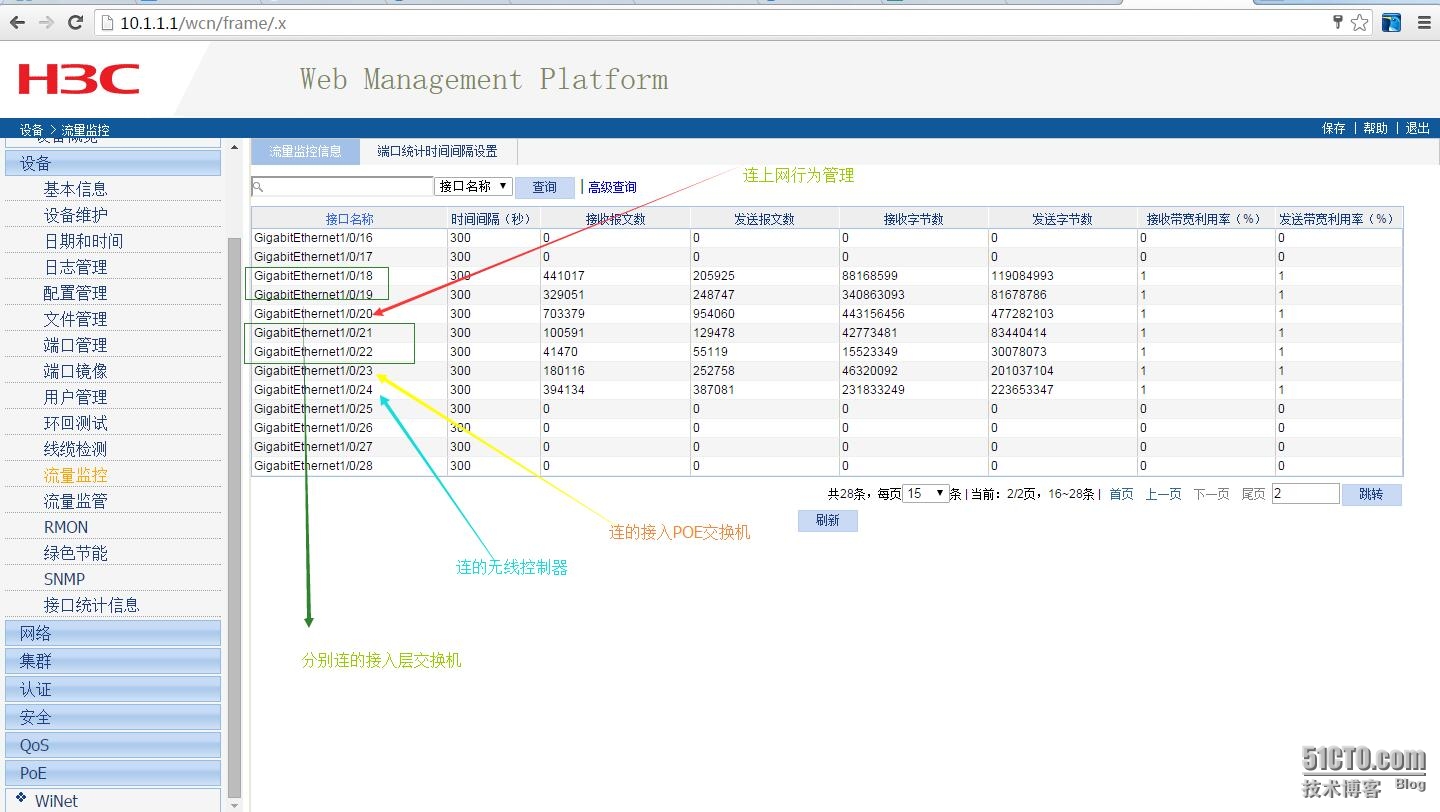
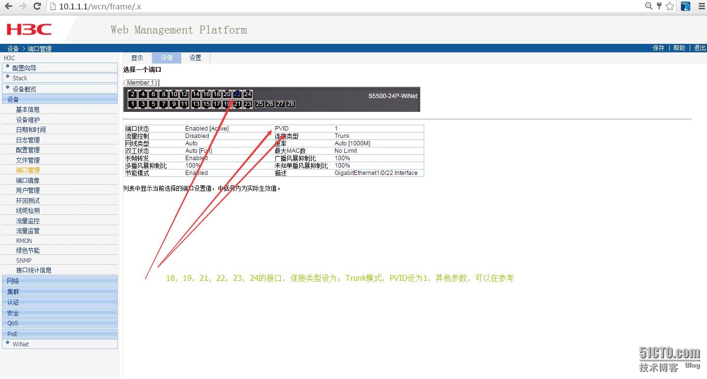
3.3 接口设为Trunk模式
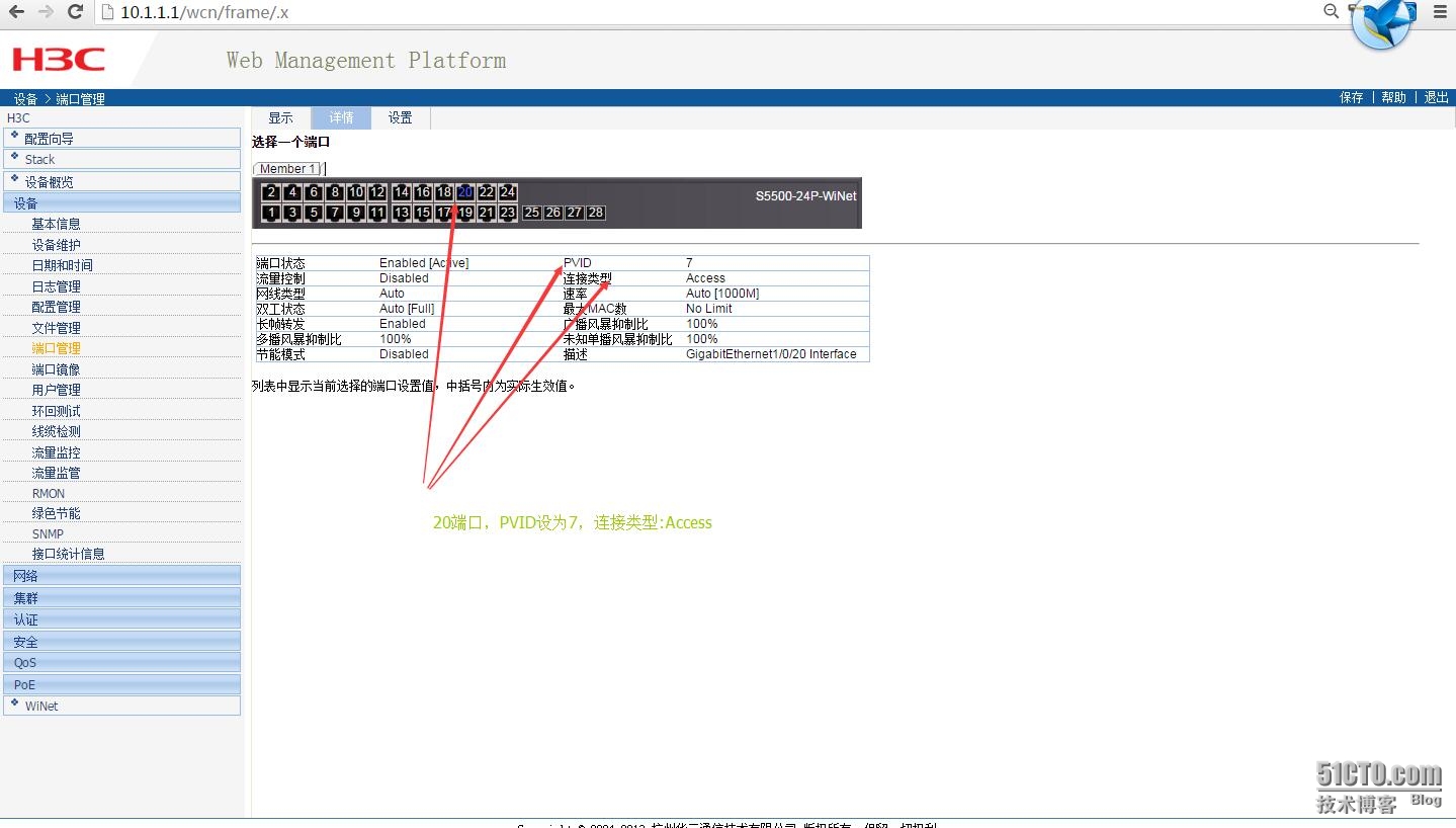
3.4 接口20的设置
相关定义
1、Trunk口,Trunk口上可以同时传送多个VLAN的包,一般用于交换机之间的链接。
2、Hybrid口,Hybrid口上可以同时传送多个VLAN的包,一般用于交换机之间的链接或交换机于服务器的链接。
3、Access口,Access口只能属于1个VLAN,一般用于连接计算机的端口。
4、Tag和Untag,tag是指vlan的标签,即vlan的id,用于指明数据包属于那个vlan,untag指数据包不属于任何vlan,没有vlan标记。
5、pvid,即端口vlan id号,是非标记端口的vlan id 设定,当非标记数据包进入交换机,交换机将检查vlan设定并决定是否进行转发。一个ip包进入交换机端口的时候,如果没有带tag头,且该端口上配置了pvid,那么,该数据包就会被打上相应的tag头!如果进入的ip包已经带有tag头(vlan数据)的话,那么交换机一般不会再增加tag头,即使是端口上配置了pvid号;当非标记数据包进入交换机。
4.接入层交换
4.1 S3110-01
4.1.2 初始配置
|
1
2
3
4
5
6
7
8
9
10
11
12
13
14
15
16
17
18
19
20
21
22
23
24
25
26
27
28
29
30
31
32
|
sysname H3C-S3110-01
#
domain default
enable
system
#
ipv6
#
telnet server
enable
#
password-recovery
enable
#
domain system
access-limit disable
state active
idle-
cut
disable
self-service-url disable
#
user-group system
group-attribute allow-guest
#
local
-user admin
password cipher 密码
authorization-attribute level 3
service-
type
telnet terminal
service-
type
web
#
user-interface aux 0
user-interface vty 0 4
authentication-mode scheme
user-interface vty 5 15
|
4.1.3 创建vlan
|
1
2
3
4
5
6
7
8
|
vlan 1
#
vlan 2
#
vlan 5 to 7
#
vlan 100
#
|
4.1.4 配置管理地址
|
1
2
|
interface Vlan-interface1
ip address 10.1.1.4 255.255.255.0
|
4.1.5 将当前的Access 端口加入到指定的VLAN2中
|
1
2
3
4
5
6
7
8
9
10
11
12
13
14
15
16
17
18
19
20
21
22
23
24
25
26
27
28
29
30
31
32
33
34
35
36
37
38
39
40
41
42
43
44
45
46
47
48
49
50
51
52
53
54
55
56
57
58
59
60
61
62
63
64
65
66
67
68
69
70
71
72
73
74
75
76
77
78
79
80
81
82
83
84
85
86
87
88
89
90
91
92
93
94
95
96
97
98
99
100
101
102
103
104
105
106
107
108
109
110
111
112
113
114
115
116
117
118
119
120
121
122
123
124
125
126
127
128
129
130
131
132
133
134
135
136
137
138
139
140
141
142
143
|
interface Ethernet1
/0/1
port access vlan 2
#
interface Ethernet1
/0/2
port access vlan 2
#
interface Ethernet1
/0/3
port access vlan 2
#
interface Ethernet1
/0/4
port access vlan 2
#
interface Ethernet1
/0/5
port access vlan 2
#
interface Ethernet1
/0/6
port access vlan 2
#
interface Ethernet1
/0/7
port access vlan 2
#
interface Ethernet1
/0/8
port access vlan 2
#
interface Ethernet1
/0/9
port access vlan 2
#
interface Ethernet1
/0/10
port access vlan 2
#
interface Ethernet1
/0/11
port access vlan 2
#
interface Ethernet1
/0/12
port access vlan 2
#
interface Ethernet1
/0/13
port access vlan 2
#
interface Ethernet1
/0/14
port access vlan 2
#
interface Ethernet1
/0/15
port access vlan 2
#
interface Ethernet1
/0/16
port access vlan 2
#
interface Ethernet1
/0/17
port access vlan 2
#
interface Ethernet1
/0/18
port access vlan 2
#
interface Ethernet1
/0/19
port access vlan 2
#
interface Ethernet1
/0/20
port access vlan 2
#
interface Ethernet1
/0/21
port access vlan 2
#
interface Ethernet1
/0/22
port access vlan 2
#
interface Ethernet1
/0/23
port access vlan 2
#
interface Ethernet1
/0/24
port access vlan 2
#
interface Ethernet1
/0/25
port access vlan 2
#
interface Ethernet1
/0/26
port access vlan 2
#
interface Ethernet1
/0/27
port access vlan 2
#
interface Ethernet1
/0/28
port access vlan 2
#
interface Ethernet1
/0/29
port access vlan 2
#
interface Ethernet1
/0/30
port access vlan 2
#
interface Ethernet1
/0/31
port access vlan 2
#
interface Ethernet1
/0/32
port access vlan 2
#
interface Ethernet1
/0/33
port access vlan 2
#
interface Ethernet1
/0/34
port access vlan 2
#
interface Ethernet1
/0/35
port access vlan 2
#
interface Ethernet1
/0/36
port access vlan 2
#
interface Ethernet1
/0/37
port access vlan 2
#
interface Ethernet1
/0/38
port access vlan 2
#
interface Ethernet1
/0/39
port access vlan 2
#
interface Ethernet1
/0/40
port access vlan 2
#
interface Ethernet1
/0/41
port access vlan 2
#
interface Ethernet1
/0/42
port access vlan 2
#
interface Ethernet1
/0/43
port access vlan 2
#
interface Ethernet1
/0/44
port access vlan 2
#
interface Ethernet1
/0/45
port access vlan 2
#
interface Ethernet1
/0/46
port access vlan 2
#
interface Ethernet1
/0/47
port access vlan 2
#
interface Ethernet1
/0/48
port access vlan 2
|
4.1.6 每个交换机有4个级联口,而且每个都以52接口配置trunk模式
|
1
2
3
|
interface GigabitEthernet1
/0/52
port link-
type
trunk
port trunk permit vlan all
|
4.1.7 配置静态路由
|
1
|
ip route-static 0.0.0.0 0.0.0.0 10.1.1.1
|
4.2 同样,另外三个交换也是同理的配置,不过在S3110-04的配置多了vlan9
|
1
2
3
4
5
6
7
8
9
10
11
12
13
14
15
16
17
18
19
20
21
22
23
24
25
26
27
28
29
30
31
32
33
34
35
36
37
38
39
40
41
42
|
#
interface Ethernet1
/0/6
port access vlan 9
#
interface Ethernet1
/0/8
port access vlan 9
#
interface Ethernet1
/0/10
port access vlan 9
#
interface Ethernet1
/0/12
port access vlan 9
#
interface Ethernet1
/0/14
port access vlan 9
#
interface Ethernet1
/0/16
port access vlan 9
#
interface Ethernet1
/0/18
port access vlan 9
#
interface Ethernet1
/0/20
port access vlan 9
#
interface Ethernet1
/0/22
port access vlan 9
#
interface Ethernet1
/0/24
port access vlan 9
#
interface Ethernet1
/0/26
port access vlan 9
#
interface Ethernet1
/0/28
port access vlan 9
#
interface Ethernet1
/0/30
port access vlan 9
#
interface Ethernet1
/0/32
port access vlan 9
|
5.接入POE交换机LS-5120
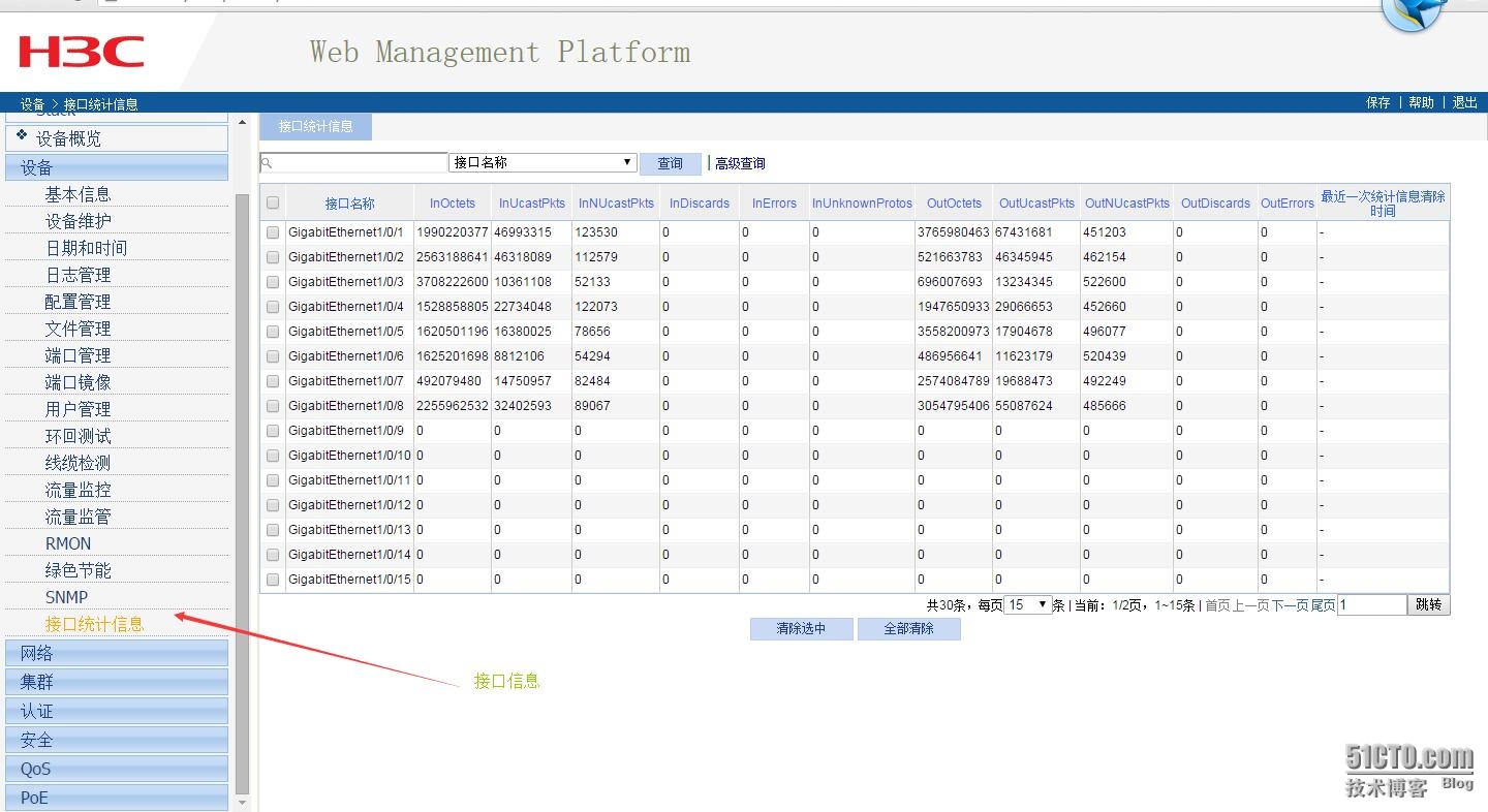
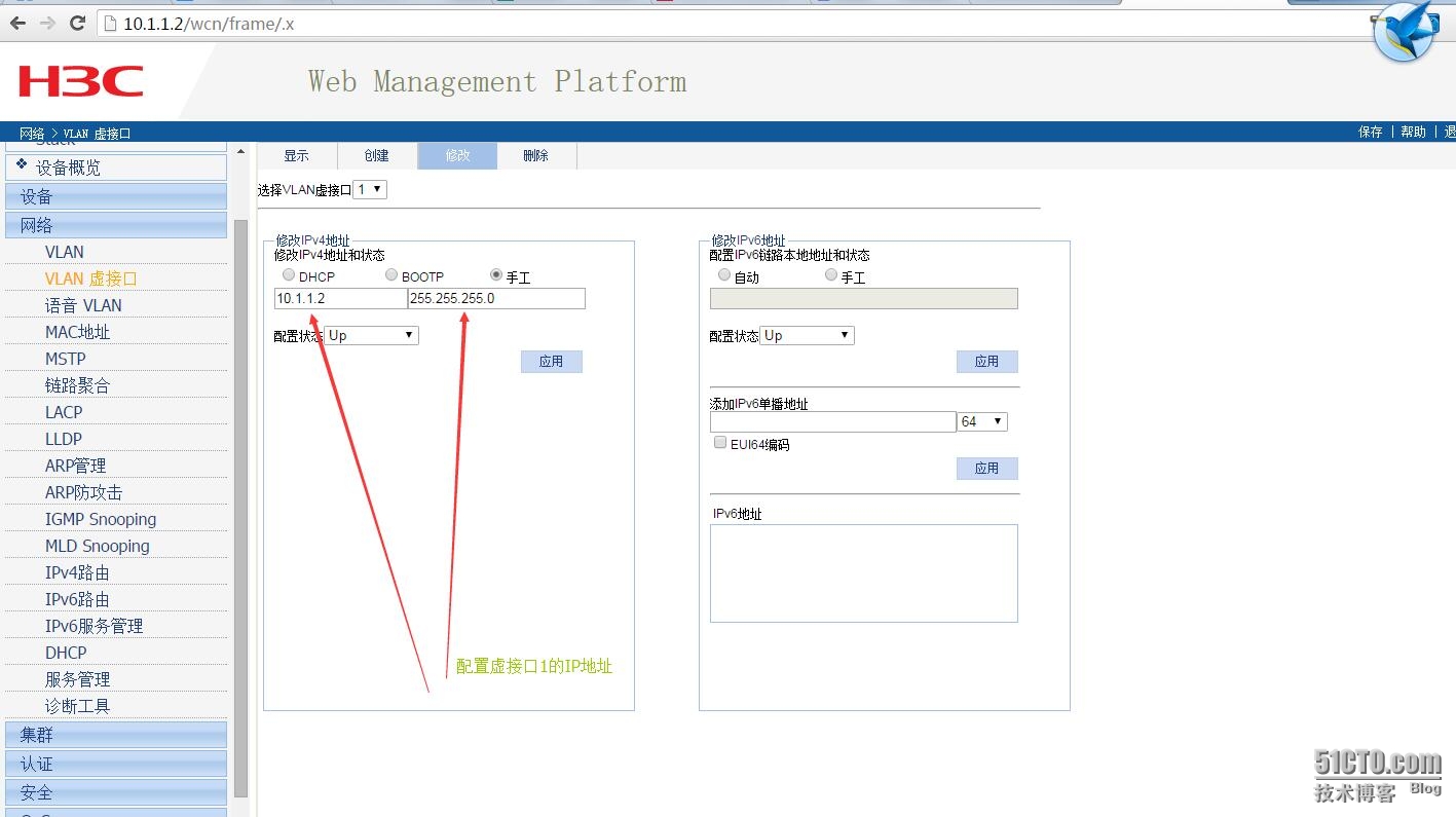
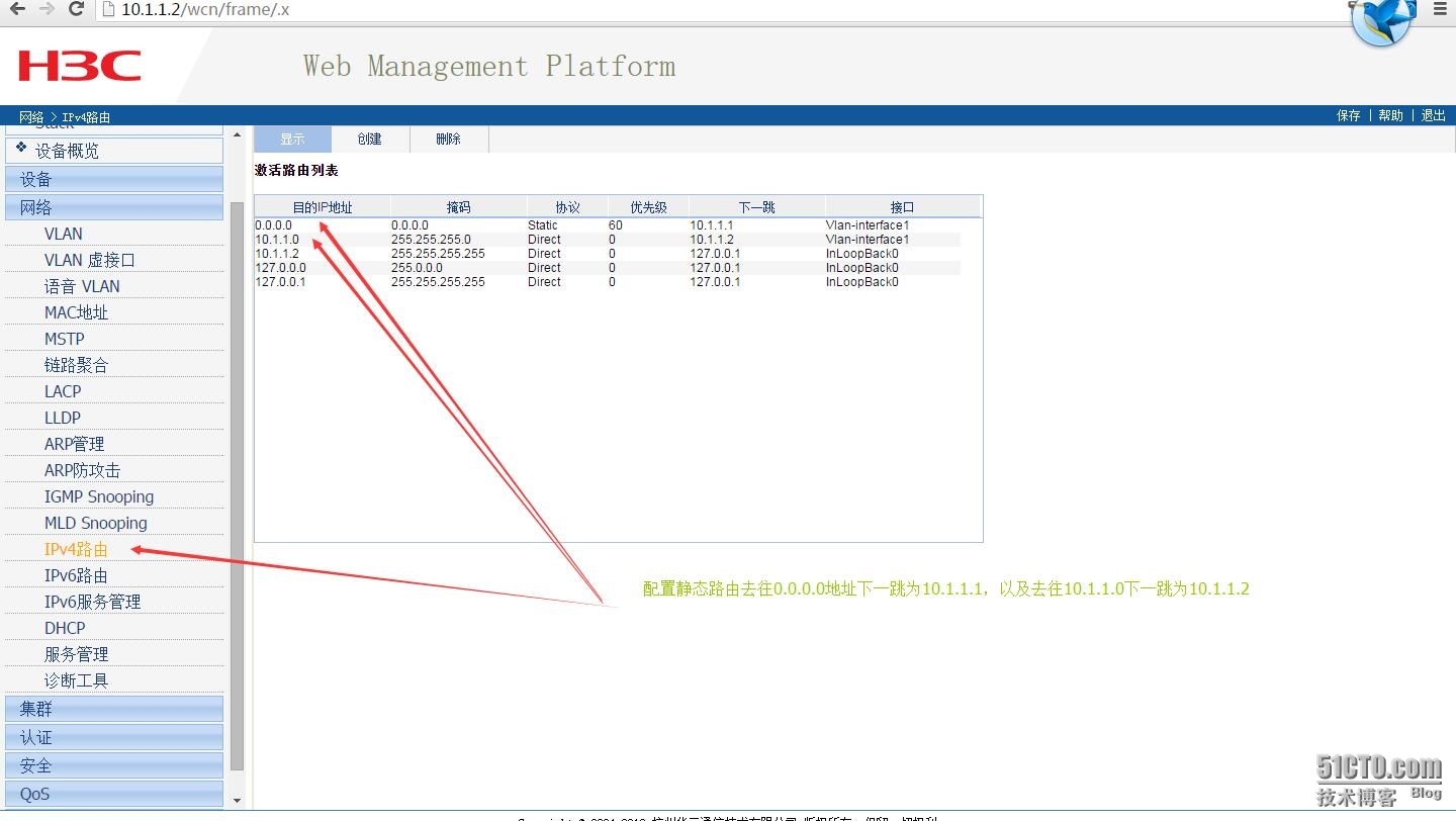
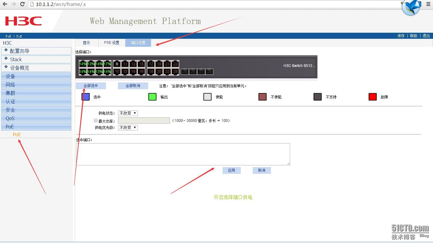
5.1 G1/0/24配置trunk模式,以及虚拟子接口1的IP,路由表设置
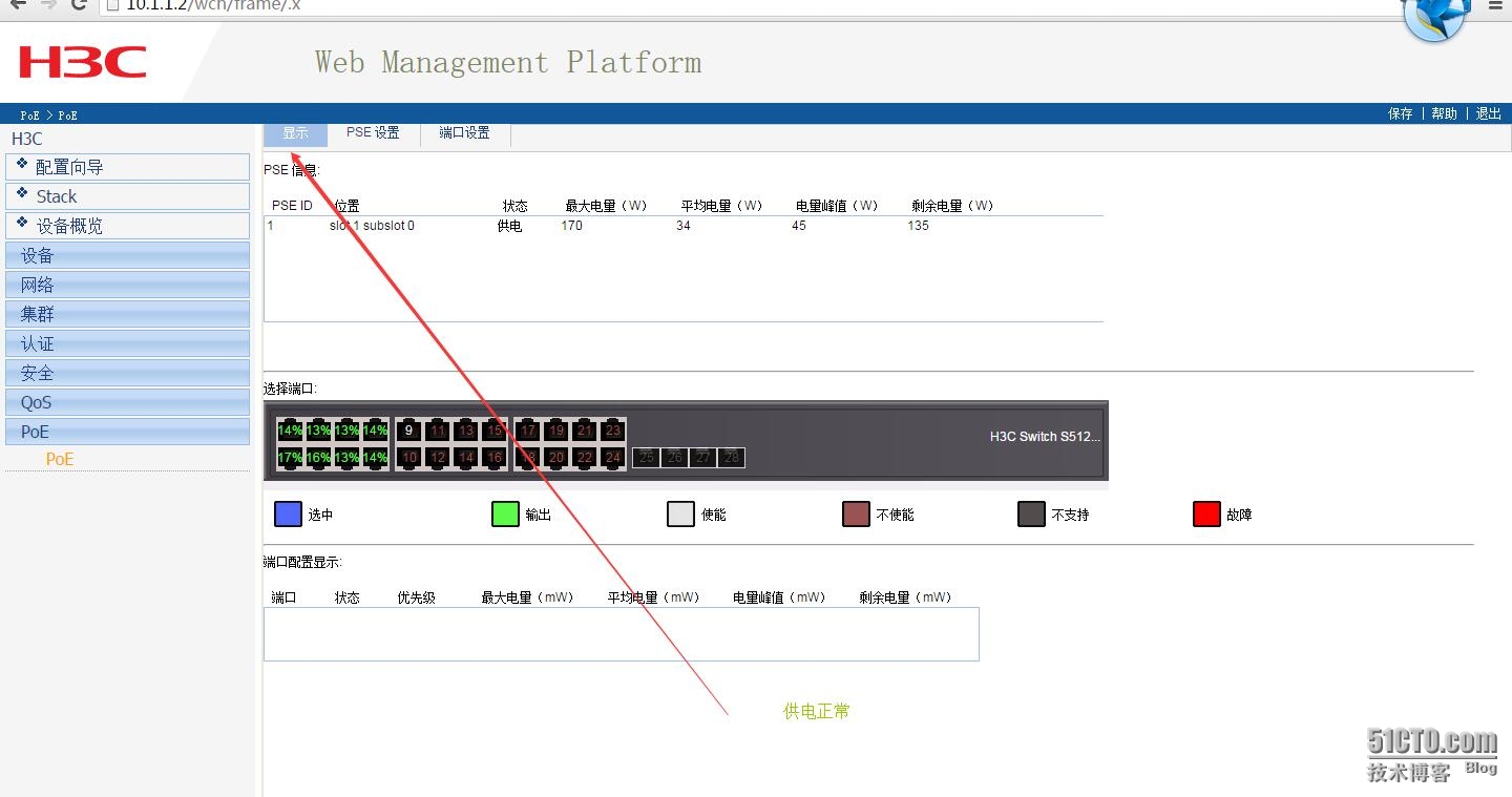
5.2 POE设置
6.无线控制器EWP-WAC360
6.1创建vlan
|
1
2
3
4
5
6
7
|
#
vlan 2
#
vlan 4 to 7
#
vlan 100
#
|
6.2 设置登录用户与密码
|
1
2
3
4
5
|
local
-user admin
password cipher 密码
authorization-attribute level 3
service-
type
telnet terminal
service-
type
web
|
6.3 射频速率设置
|
1
2
3
4
5
6
7
|
wlan rrm
dot11a mandatory-rate 6 12 24
dot11a supported-rate 9 18 36 48 54
dot11b mandatory-rate 1 2
dot11b supported-rate 5.5 11
dot11g mandatory-rate 1 2 5.5 11
dot11g supported-rate 6 9 12 18 24 36 48 54
|
6.4 无线接入服务,
6.4.1一个本公司,另一个是客户访问
|
1
2
3
4
5
6
|
wlan service-template 2 crypto
ssid Company
bind WLAN-ESS 2
cipher-suite ccmp
security-ie rsn
service-template
enable
|
6.4.2 另一个是客户访问
|
1
2
3
4
5
6
7
|
#
wlan service-template 3 crypto
ssid CompanyVistor
bind WLAN-ESS 3
cipher-suite ccmp
security-ie rsn
service-template
enable
|
6.5接口管理
6.5.1 配置它的管理IP地址
|
1
2
|
interface Vlan-interface100
ip address 10.1.100.254 255.255.255.0
|
6.5.1 把G1/0/1接口切换为二层模式,作为一个二层以太网端口使用,同时
|
1
2
3
4
|
interface GigabitEthernet1
/0/1
port link-mode bridge
port link-
type
trunk
port trunk permit vlan all
|
6.6 创建预共享密钥
6.6.1 且允许客户访问vlan6
|
1
2
3
4
5
|
interface WLAN-ESS2
port access vlan 6
port-security port-mode psk
port-security tx-key-
type
11key
port-security preshared-key pass-phrase cipher
|
6.6.2且允许客户访问vlan5
|
1
2
3
4
5
|
interface WLAN-ESS3
port access vlan 5
port-security port-mode psk
port-security tx-key-
type
11key
port-security preshared-key pass-phrase cipher
|
6.7 AP设置,用到序列号
6.7.1 创建AP名称
|
1
2
3
4
5
6
7
8
9
10
11
12
13
14
|
wlan ap-group default_group
ap ap1
ap ap2
ap ap3
ap ap4
ap ap5
ap ap6
ap ap7
ap ap8
ap ap9
dot11a service-template 1
dot11bg service-template 1
dot11a radio
enable
dot11bg radio
enable
|
6.7.1 添加AP
6.7.1.1
|
1
2
3
4
5
6
7
8
9
10
|
wlan ap ap2 model WAP722
id
2
serial-
id
219801A0Q19154G00032
radio 1
service-template 2
service-template 3
radio
enable
radio 2
service-template 2
service-template 3
radio
enable
|
6.7.1.2
|
1
2
3
4
5
6
7
8
9
10
|
wlan ap ap3 model WAP722
id
3
serial-
id
219801A0Q19154G00025
radio 1
service-template 2
service-template 3
radio
enable
radio 2
service-template 2
service-template 3
radio
enable
|
6.7.1.3
|
1
2
3
4
5
6
7
8
9
10
|
wlan ap ap4 model WAP722
id
4
serial-
id
219801A0Q19154G00052
radio 1
service-template 2
service-template 3
radio
enable
radio 2
service-template 2
service-template 3
radio
enable
|
6.7.1.4
|
1
2
3
4
5
6
7
8
9
10
|
wlan ap ap5 model WAP722
id
5
serial-
id
219801A0Q19154G00338
radio 1
service-template 2
service-template 3
radio
enable
radio 2
service-template 2
service-template 3
radio
enable
|
6.7.1.5
|
1
2
3
4
5
6
7
8
9
10
|
wlan ap ap6 model WAP722
id
6
serial-
id
219801A0Q19154G00110
radio 1
service-template 2
service-template 3
radio
enable
radio 2
service-template 2
service-template 3
radio
enable
|
6.7.1.6
|
1
2
3
4
5
6
7
8
9
10
|
wlan ap ap7 model WAP722
id
7
serial-
id
219801A0Q19154G00195
radio 1
service-template 2
service-template 3
radio
enable
radio 2
service-template 2
service-template 3
radio
enable
|
6.7.1.7
|
1
2
3
4
5
6
7
8
9
10
|
wlan ap ap8 model WAP722
id
8
serial-
id
219801A0Q19154G00080
radio 1
service-template 2
service-template 3
radio
enable
radio 2
service-template 2
service-template 3
radio
enable
|
6.7.1.8
|
1
2
3
4
5
6
7
8
9
10
|
wlan ap ap9 model WAP722
id
9
serial-
id
219801A0Q19154G00038
radio 1
service-template 2
service-template 3
radio
enable
radio 2
service-template 2
service-template 3
radio
enable
|
6.8 配置静态路由
|
1
|
ip route-static 0.0.0.0 0.0.0.0 10.1.100.253
|
6.9 最后开启telnet
|
1
2
3
4
|
user-interface con 0
user-interface vty 0 4
authentication-mode scheme
user privilege level 3
|
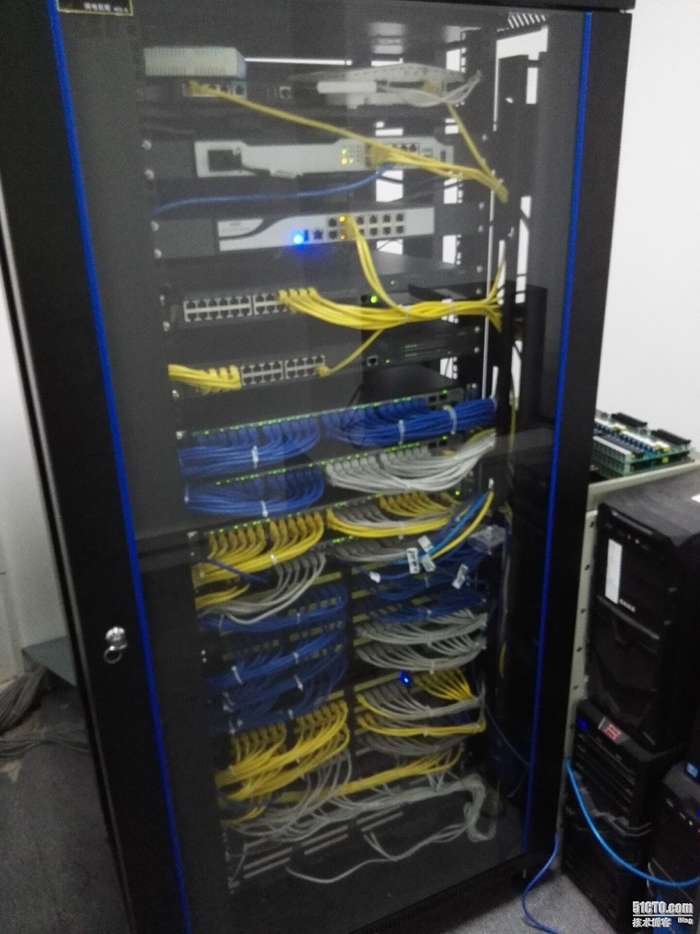
五、效果图
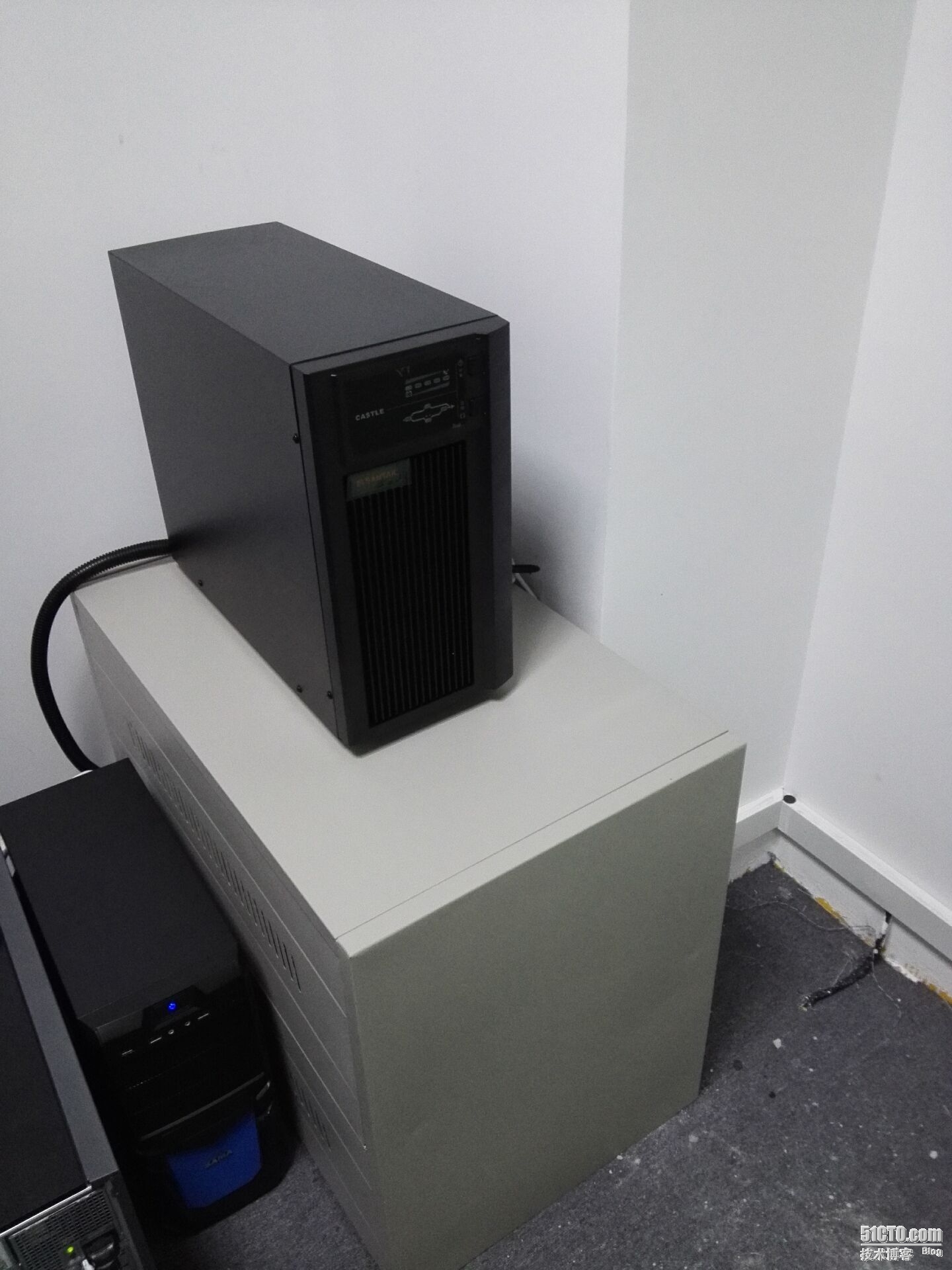
机柜是买小,线道上,都塞满了,本地服务器也好几台,没有多余空间,就买了塔式的(本地服务器都是用来集群测试用的)。这次机房建设没有很好考虑到扩展性!吸取教训,为一下次完善机房做准备吧!
