做嵌入式开发,UART几乎是必不可少的,调试串口、GPS、GPRS、Bluetooth等模块很多都是用的UART接口。时下火热的IoT也不乏UART的身影,串口的BLE、WIFI、Zigbee、Lora等等模块,一堆一堆。前一篇提到的NUC972竟然内置了11个UART,也就可以理解了。虽然之前已基于串口做了很多工具软件,如S3C2410的烧录助手、WinCE串口调试助手、GPRS拨号助手、蓝牙模块调试助手等等,但现在搞IoT再弄串口,还是有必要整理一下这方面的知识,毕竟IoT跟教学实验设备甚至车载导航有很大不同,是不能够随便重启的。IoT产品可靠性要求极高,避免自己掉到坑里或者挖坑害了战友,花点时间整理UART相关知识是非常值得的。本篇转载的文章主要介绍了UART的基本特性,个人感觉写的非常好,具体如下。
Introduction to the standard serial bus
UART (Universal Asynchronous Receiver/Transmitter) is one of the earliest modes of communication applied to computers, and its origins go back at least as far as the 1960s when it was used to connect minicomputers toteletypewriter machines — 'teletypes', as they were more commonly called. These were essentially electric keyboards able to transmit keystrokes to, and to print out responses from, the host. During the 1970s, UART was employed to allow early microcomputers to store and load programs and data from cassette tapes. In the following decades it was used to get personal computers talking to online services via modems.
Until the arrival of USB, personal computers had serial ports to connect to other devices. UART was the underlying means of communication. Nowadays, UART is used primarily by microcontroller-based gadgets and by more sophisticated devices, including the imp.
UART has had many names, but whatever it has been called, it always involves sending data over two wires — one for transmission, the other to receive incoming data. The information is transmitted one binary bit at a time; as such it is a 'serial' communications method. These bits are grouped together into 'frames' — a set format for conveying one meaningful piece of data.
UART is said to be 'universal' because its parameters — speed, data size and so on — are not fixed and can be configured to meet the needs of a given communication requirement, though this means that both sides of the conversation need to have already agreed on these parameters. It is 'asynchronous' because it doesn't require a sender-provided clock to synchronize the transmission and receipt of data.
UART Signalling
Because there is no clock signal per se, a 'start bit' is added sent first to tell the receiver to listen out for data. The receiver watches for a logic 'high' falling to logic 'low'. The receiver synchronizes its own bus clock to that bit.
Following the start bit come the bits that that make up the 'word' being sent, with bit zero, the least significant bit, being sent first. The bits are sent as pulses on the wire at specific time intervals, set at both ends of the link to previously agreed values. The receiver looks at the voltage on the wire at these times; if it sees a logic high, it records a binary digit 1, or a 0 if the line is 'low', or 0V. The receiver checks half way between the start and the end of the pulse to ensure it doesn't mis-read the voltage on the line during the brief intervals while the voltage is rising or falling.
If the two devices have agreed to use a 'parity bit' for rudimentary error-checking, that is calculated and sent next, in sync with the data that has been transmitted thus far. Finally, at least one 'stop bit' is sent by the transmitter.
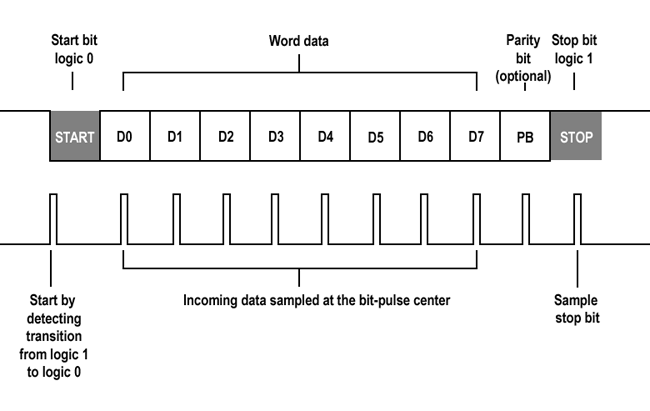
A UART frame
Word length, parity availability and type, and the number of stop bits all have to be agreed in advance.
Because UART uses two wires — one, connecting device A's transmitter to device B's receiver, and the other, device B's transmitter to device A's receiver — the two participants can send each other data simultaneously, a mode of communications called 'full duplex'.
原文链接: https://electricimp.com/docs/resources/uart/
该网站有关IIC总线和SPI总线的介绍也相当不错,详见https://electricimp.com/docs/resources/index_hardware
UART WIKI: https://en.wikipedia.org/wiki/Universal_asynchronous_receiver/transmitter