目前,在博客园上,相对写得比较好的两个关于Direct2D的教程系列,分别是万一的Direct2D系列和zdd的Direct2D系列。有兴趣的网友可以去看看。本系列也是介绍Direct2D的教程,是基于Windows API Code Pack 1.1的Direct2D的教程,如果要调试文中的代码的话,还得参考前文 Direct2D教程I——简介及首个例子 下载导入Windows API Code Pack 1.1的动态库
在前文 Direct2D教程I——简介及首个例子 简单介绍了Direct2D,并给了一个简单的示例。接下来,本文对一些基本的绘图命令做个介绍
绘制基本图形:直线、矩形、圆角矩形、椭圆
和GDI+类似,在RenderTarget对象下有各个绘图命令(GDI+是在Graphics对象下有各个绘图命令),下面是各个基本图形的绘图命令的函数原型
直线:
Public Sub DrawLine(firstPoint As Direct2D1.Point2F, secondPoint As Direct2D1.Point2F, brush As Direct2D1.Brush, skrokeWidth As Single, strokeStyle As Direct2D1.StrokeStyle)
矩形:
Public Sub DrawRectangle(rect As Direct2D1.RectF, brush As Direct2D1.Brush, strokeWidth As Single)
Public Sub DrawRectangle(rect As Direct2D1.RectF, brush As Direct2D1.Brush, strokeWidth As Single, strokeStyle As Direct2D1.StrokeStyle)
Public Sub FillRectangle(rect As Direct2D1.RectF, brush As Direct2D1.Brush)
圆角矩形:
Public Sub DrawRoundedRectangle(roundedRect As Direct2D1.RoundedRect, brush As Direct2D1.Brush, strokeWidth As Single)
Public Sub DrawRoundedRectangle(roundedRect As Direct2D1.RoundedRect, brush As Direct2D1.Brush, strokeWidth As Single, strokeStyle As Direct2D1.StrokeStyle)
Public Sub FillRoundedRectangle(roundedRect As Direct2D1.RoundedRect, brush As Direct2D1.Brush)
椭圆:
Public Sub DrawEllipse(ellipse As Direct2D1.Ellipse, brush As Direct2D1.Brush, strokeWidth As Single)
Public Sub DrawEllipse(ellipse As Direct2D1.Ellipse, brush As Direct2D1.Brush, strokeWidth As Single, strokeStyle As Direct2D1.StrokeStyle)
Public Sub FillEllipse(ellipse As Direct2D1.Ellipse, brush As Direct2D1.Brush)
从上面的函数原型可以看出,以Draw开头的函数都是绘制函数。以Fill开头的函数都是填充函数。绘制函数的线宽由strokeWidth参数指定,绘制函数的线型由strokeStyle参数指定(默认是实线)。和GDI+不同的是,在Direct2D中,不再区分Brush(画刷)和Pen(画笔)对象,而统一用Brush(画刷)对象,在用Brush(画刷)绘制线的时候再指定线宽和线型参数。
从参数strokeWidth和参数strokeStyle来看,都带有单词stroke。熟悉PS的都知道,stroke指的是描边,在PS中描边的位置分为“外部”、“内部”、“居中”。那么在Direct2D中,这里的描边的位置在哪儿呢?我们用代码实验一下。
说明:为了代码的复用,我们把前文中的_d2DFactory和_renderTarget修饰限定词从Private改为Protected。这样在后面的例子中直接继承前文的类,也可以直接用_d2DFactory和_renderTarget这两个对象。
先给出Point2F、RectF、RoundedRect、Ellipse这四个类的原型定义,参数都简介明了,不再详述
Direct2D1. Point2F(x As Single, y As Single)
Direct2D1. RectF(left As Single, top As Single, right As Single, buttom As Single)
Direct2D1. RoundedRect(rect As Direct2D1. RectF, radiusX As Single, radiusY As Single)
Direct2D1. Ellipse(point As Direct2D1. Point2F, radiusX As Single, radiusY As Single)
下面是实验示例代码
Public Class clsDirect2DSample2
Inherits clsDirect2DSample
Public Shadows Sub Render()
If Not _renderTarget Is Nothing Then
With _renderTarget
.BeginDraw()
Dim F1 As New Direct2D1. RectF(0, 0, 100, 50)
Dim F2 As New Direct2D1. RectF(200, 200, 300, 250)
Dim B As Direct2D1. SolidColorBrush = _renderTarget.CreateSolidColorBrush( New Direct2D1. ColorF(1, 0, 0))
_renderTarget.DrawRectangle(F1, B, 10)
_renderTarget.DrawRectangle(F2, B, 10)
.EndDraw()
End With
End If
End Sub
End Class
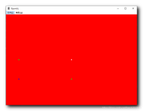
从上图的代码来看,在(0,0)位置上画了一个100*50的矩形,描边宽度10px。在(200,200)位置上画了一个矩形,描边宽度10px,如下图所示

从上面的效果可以看出两点:
一是左上角的矩形说明,Direct2D中的描边类型应该是“居中”;
二是右边的矩形说明Direct2D中的RectF定义和原本GDI+中的RectangleF定义不同,Direct2D中的RectF中后两个参数是右下角的坐标,而GDI+中的RectangleF中的后两个参数指的是矩形的宽和高。
线型(StrokeStyle)的设置
在上面的函数原型中,线型是由参数strokeStyle决定的,它是StrokeStyle类。这个类不能直接初始化,必须由D2DFactory对象的CreateStrokeStyle函数创建(Direct2D中有不少的类不能直接初始化,必须由D2DFactory或RenderTarget对象的相应的函数创建,如上面的SolidColorBrush对象就必须由RenderTarget对象的CreateSolidColorBrush函数创建)。
先看看CreateStrokeStyle函数的原型定义:
Public Function CreateStrokeStyle(strokeStyleProperties As Direct2D1.StrokeStyleProperties) As Direct2D1.StrokeStyle
Public Function CreateStrokeStyle(strokeStyleProperties As Direct2D1.StrokeStyleProperties, dashes() As Single) As Direct2D1.StrokeStyle
主要是通过strokeStyleProperties参数来设置线型,来看看StrokeStyleProperties结构及其参数对象的原型定义。
Direct2D1.StrokeStyleProperties(startCap As Direct2D1.CapStyle, endCap As Direct2D1.CapStyle, dashCap As Direct2D1.CapStyle, _
lineJoin As Direct2D1.LineJoin, miterLimit As Single, _
dashStyle As Direct2D1.DashStyle, dashOffset As Single)
Public Enum CapStyle
Flat = 0
Square = 1
Round = 2
Triangle = 3
End Enum
Public Enum LineJoin
Miter = 0
Bevel = 1
Round = 2
MiterOrBevel = 3
End Enum
Public Enum DashStyle
Solid = 0
Dash = 1
Dot = 2
DashDot = 3
DashDotDot = 4
Custom = 5
End Enum
其中CapStyle枚举指的是线端的线头类型,分别是Flat(平整,即无)、Square(方块)、Round(圆)、Triangle(三角)。和GDI+中的DashCap枚举类似,多了一个Square(方块),而在下面的例子中会说明Flat和Square的区别。参数startCap决定线起点的线头类型、endCap决定线终点的线头类型、dashCap决定中间划线端的线头类型。
而DashStyle枚举指的是线型,分别是Solid(实线)、Dash(划线)、Dot(点线)、DashDot(点划线)、DashDotDot(点点划线)、Custom(自定义)。和GDI+中的DashStyle一样。
参数dashOffset指的是点划线的偏移量
下面的代码是对上面的两个枚举的演示,请注意枚举CapStyle中的Flat和Square的区别。
Public Class clsDirect2DSample3
Inherits clsDirect2DSample
Public Shadows Sub Render()
If Not _renderTarget Is Nothing Then
With _renderTarget
.BeginDraw()
Dim B As Direct2D1. SolidColorBrush = _renderTarget.CreateSolidColorBrush( New Direct2D1. ColorF(1, 0, 0))
Dim SP As New Direct2D1. StrokeStyleProperties()
Dim S As Direct2D1. StrokeStyle
SP.StartCap = Direct2D1. CapStyle.Flat
SP.EndCap = Direct2D1. CapStyle.Flat
S = _d2DFactory.CreateStrokeStyle(SP)
_renderTarget.DrawLine( New Direct2D1. Point2F(10, 20), New Direct2D1. Point2F(200, 20), B, 8, S)
SP.StartCap = Direct2D1. CapStyle.Square
SP.EndCap = Direct2D1. CapStyle.Square
S = _d2DFactory.CreateStrokeStyle(SP)
_renderTarget.DrawLine( New Direct2D1. Point2F(10, 40), New Direct2D1. Point2F(200, 40), B, 8, S)
SP.StartCap = Direct2D1. CapStyle.Round
SP.EndCap = Direct2D1. CapStyle.Round
S = _d2DFactory.CreateStrokeStyle(SP)
_renderTarget.DrawLine( New Direct2D1. Point2F(10, 60), New Direct2D1. Point2F(200, 60), B, 8, S)
SP.StartCap = Direct2D1. CapStyle.Triangle
SP.EndCap = Direct2D1. CapStyle.Triangle
S = _d2DFactory.CreateStrokeStyle(SP)
_renderTarget.DrawLine( New Direct2D1. Point2F(10, 80), New Direct2D1. Point2F(200, 80), B, 8, S)
SP.StartCap = Direct2D1. CapStyle.Flat
SP.EndCap = Direct2D1. CapStyle.Flat
SP.DashCap = Direct2D1.CapStyle.Round
SP.DashStyle = Direct2D1. DashStyle.Solid
S = _d2DFactory.CreateStrokeStyle(SP)
_renderTarget.DrawLine( New Direct2D1. Point2F(10, 120), New Direct2D1. Point2F(200, 120), B, 6, S)
SP.DashStyle = Direct2D1. DashStyle.Dash
S = _d2DFactory.CreateStrokeStyle(SP)
_renderTarget.DrawLine( New Direct2D1. Point2F(10, 140), New Direct2D1. Point2F(200, 140), B, 6, S)
SP.DashStyle = Direct2D1. DashStyle.Dot
S = _d2DFactory.CreateStrokeStyle(SP)
_renderTarget.DrawLine( New Direct2D1. Point2F(10, 160), New Direct2D1. Point2F(200, 160), B, 6, S)
SP.DashStyle = Direct2D1. DashStyle.DashDot
S = _d2DFactory.CreateStrokeStyle(SP)
_renderTarget.DrawLine( New Direct2D1. Point2F(10, 180), New Direct2D1. Point2F(200, 180), B, 6, S)
SP.DashStyle = Direct2D1. DashStyle.DashDotDot
S = _d2DFactory.CreateStrokeStyle(SP)
_renderTarget.DrawLine( New Direct2D1. Point2F(10, 200), New Direct2D1. Point2F(200, 200), B, 6, S)
.EndDraw()
End With
End If
End Sub
End Class

上面四条线是演示枚举CapStyle的四种类型,注意第一条线是Flat,第二条线是Square。虽然都是方形,但是很明显第二条线比第一条线两边还多出一点(方形线帽)
下面五条线是演示枚举DashStyle表示的五个线型。注意:上面代码中红色的部分,DashCap不能设置为Direct2D1.CapStyle.Flat,如果设置为Flat,则所有的点都不见了;设置其他三种类型分别代表不同的点(方形点、圆点、菱形点)。
再说说枚举DashStyle中的Custom线型。设定为Custom后,必须用一个数组来指定自定义划线的线型。数组按照{实、空、实、空……}顺序来指定各部分的长度,单位是线宽。
例如{2,2}表示2线宽长的实线和2线宽长的空白组成的划线,也就是枚举DashStyle中的Dash
{0,2}表示0线宽长的实线和2线宽长的空白组成的划线,就是枚举DashStyle中的Dot。这也解释了DashCap设置为Direct2D1.CapStyle.Flat时,为何点不见了(设置为其他值时,点实际上是由线头组成的,点本身的长度为0)。
以此类推,{2,2,0,2}表示DashStyle中的DashDot,{2,2,0,2,0,2}表示DashStyle中的DashDotDot
要注意的是,只有枚举DashStyle设置为Custom时,才能传递数组,否则会直接报错的。
最后说说LineJoin枚举,指的是连接两条线的连接方式。分别是Miter(折角)、Bevel(倒角)、Round(圆角)、MiterOrBevel(折角或倒角)。和GDI+中的LineJoin枚举类似,只是MiterOrBevel好像对应GDI+中LineJoin枚举中的MiterClipped。
说说MiterOrBevel,当折角的值没有超过指定的值(系统指定)时,是Miter(折角),反之超过的话是Bevel(倒角)。
参数miterLimit是指折角的限制,低于限制时会自动添加倒角。参数miterLimit最小是1。注意的是miterLimit参数并不是配合LineJoin使用。当miterLimit设置为1的时候,下面的例子中,LineJoin枚举设置成Miter、Bevel、MiterOrBevel效果是一样的。当miterLimit设置为3的时候,LineJoin枚举设置成Miter、Bevel、MiterOrBevel效果才是不一样的
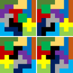
下面是LineJoin的示例,由于是演示两条线的连接,故用了一些后面才会详述的代码。不过,不影响我们理解枚举LineJoin的各个设置值的意义。
左上是Miter,右上是Bevel,左下是Round,右下是MiterOrBevel
Public Class clsDirect2DSample4
Inherits clsDirect2DSample
Public Shadows Sub Render()
If Not _renderTarget Is Nothing Then
With _renderTarget
.BeginDraw()
Dim B As Direct2D1. SolidColorBrush = _renderTarget.CreateSolidColorBrush( New Direct2D1. ColorF(1, 0, 0))
Dim SP As New Direct2D1. StrokeStyleProperties()
Dim S As Direct2D1. StrokeStyle
Dim PG As Direct2D1. PathGeometry
Dim sink As Direct2D1. GeometrySink
PG = _d2DFactory.CreatePathGeometry
sink = PG.Open
sink.BeginFigure( New Direct2D1. Point2F(17, 17), Direct2D1. FigureBegin.Hollow)
sink.AddLine( New Direct2D1. Point2F(45, 85))
sink.AddLine( New Direct2D1. Point2F(85, 45))
sink.AddLine( New Direct2D1. Point2F(85, 125))
sink.AddLine( New Direct2D1. Point2F(165, 17))
sink.EndFigure(Direct2D1. FigureEnd.Open)
sink.Close()
SP.LineJoin = Direct2D1. LineJoin.Miter
SP.MiterLimit = 3
S = _d2DFactory.CreateStrokeStyle(SP)
.DrawGeometry(PG, B, 10, S)
PG = _d2DFactory.CreatePathGeometry
sink = PG.Open
sink.BeginFigure( New Direct2D1. Point2F(217, 17), Direct2D1. FigureBegin.Hollow)
sink.AddLine( New Direct2D1. Point2F(245, 85))
sink.AddLine( New Direct2D1. Point2F(285, 45))
sink.AddLine( New Direct2D1. Point2F(285, 125))
sink.AddLine( New Direct2D1. Point2F(365, 17))
sink.EndFigure(Direct2D1. FigureEnd.Open)
sink.Close()
SP.LineJoin = Direct2D1. LineJoin.Bevel
SP.MiterLimit = 3
S = _d2DFactory.CreateStrokeStyle(SP)
.DrawGeometry(PG, B, 10, S)
PG = _d2DFactory.CreatePathGeometry
sink = PG.Open
sink.BeginFigure( New Direct2D1. Point2F(17, 217), Direct2D1. FigureBegin.Hollow)
sink.AddLine( New Direct2D1. Point2F(45, 285))
sink.AddLine( New Direct2D1. Point2F(85, 245))
sink.AddLine( New Direct2D1. Point2F(85, 325))
sink.AddLine( New Direct2D1. Point2F(165, 217))
sink.EndFigure(Direct2D1. FigureEnd.Open)
sink.Close()
SP.LineJoin = Direct2D1. LineJoin.Round
SP.MiterLimit = 3
S = _d2DFactory.CreateStrokeStyle(SP)
.DrawGeometry(PG, B, 10, S)
PG = _d2DFactory.CreatePathGeometry
sink = PG.Open
sink.BeginFigure( New Direct2D1. Point2F(217, 217), Direct2D1. FigureBegin.Hollow)
sink.AddLine( New Direct2D1. Point2F(245, 285))
sink.AddLine( New Direct2D1. Point2F(285, 245))
sink.AddLine( New Direct2D1. Point2F(285, 325))
sink.AddLine( New Direct2D1. Point2F(365, 217))
sink.EndFigure(Direct2D1. FigureEnd.Open)
sink.Close()
SP.LineJoin = Direct2D1. LineJoin.MiterOrBevel
SP.MiterLimit = 3
S = _d2DFactory.CreateStrokeStyle(SP)
.DrawGeometry(PG, B, 10, S)
.EndDraw()
End With
End If
End Sub
End Class
下面是效果图

从上图能看出四种类型的不同。左上是Miter,右上是Bevel,左下是Round,右下是MiterOrBevel
在网上搜到的官网的Direct2D的帮助文档。http://msdn.microsoft.com/zh-cn/library/windows/desktop/dd370990(v=vs.85).aspx,可以参考一下。