FRIDAY, MAY 1, 2009
OpenGL ES From the Ground Up, Part 4: Let There Be Light!
Continuing on with OpenGL ES for the iPhone, let's talk about light. So far, we haven't done anything with light. Fortunately, OpenGL still lets us see what's going on if we don't configure any lights. It just provides a very flat overall lighting so that we can see stuff. But without defined lights, things have a tendency to look rather flat, as you saw in apps we wrote back in
part 2.

GL_FLAT rendering of an icosahedron. State of the art real-time rendering... 15 years ago.
GL_FLAT treats every pixel on a given triangle exactly the same in terms of lighting. Every pixel on a polygon will have the same color, shade, everything. It gives enough visual cues to have some three-dimensionality and it's computationally a lot cheaper than calculating every pixel differently, but flat shaded objects tend not to look very real. Now, there might be a certain retro value to using GL_FLAT at times, but to make your 3D objects look as realistic as possible you're going to want to go with the GL_SMOOTH drawing mode, which uses a smooth but fairly fast shading algorithm called Gouraud shading. GL_SMOOTH is the default value.
The only reason I bring it up is at all is simply because some of the stuff discussed toward the end of this article doesn't work exactly the same if you're using GL_FLAT shading. Given how antiquated and unnecessary GL_FLAT is for most purposes, I didn't want to spend time covering it.
The first thing we need to do is enable lights. By default, manually-specified lights are disabled. Let's turn that feature on now. Go into GLViewController.mand add the code in bold below to the setupView: method:
Typically, lights are something you will enable once during setup, and not touch again. It's not a feature you should be turning on and off before and after drawing. There might be some odd cases where you turned them on or off during your program's execution, but most of the time you just enable when your app launches. That single line of code is all it takes to enable lighting in OpenGL ES. Any idea what happens if we run the program now?

The way lights are enabled is a little odd. OpenGL ES allows you to create up to 8 light sources. There is a constant that corresponds to each of these possible lights, which run from GL_LIGHT0 to GL_LIGHT7. You can use any combination of these five lights, though it is customary to start with GL_LIGHT0 for your first light source, and then go to GL_LIGHT1 for the next, and so on as you need more lights. Here's how you would "turn on" the first light, GL_LIGHT0>:
Once you've enabled a light, you have to specify some attributes of that light. For starters, there are three different component colors that are used to define a light. Let's look at those first.
The following illustration shows what effect each component has on the resulting image.

Source image from Wikimedia Commons, modified as allowed by license.
The specular component defines direct light that is very direct and focused and which tends to reflect back to the viewer such that it forms a "hot spot" or shine on the object. The size of the spot can vary based on a number of factors, but if you see an area of more pronounced light such as the two white dots on the yellow sphere above, that's generally going to be coming from the specular component of one or more lights.
The diffuse component defines flat, fairly even directional light that shines on the side of objects that faces the light source.
Ambient light is light with no apparent source. It is light that has bounced off of so many things that its original source can't be identified. The ambient component defines light that shines evenly off of all sides of all objects in the scene.
Here's how you would specify the ambient component of a light to a very dim white light:
Using a low ambient value like this will make the lighting in your scene more dramatic, but it also means that the side of an object that is not facing a light, or objects that have other objects between them and the light will not be seen very well in your scene.
Here's an example of specifying the diffuse component for the first light in a scene:
Here's an example of setting the specular component:
That position would place the first light behind the viewer a little to the right and a little ways up (or a lot to the right and up if the OpenGL units represent large values in your virtual world).
Those are the attributes that you'll set for nearly all lights. If you don't set a value for one of the components, it will default that component to black {0.0, 0.0, 0.0, 1.0}. If you don't define a position, it will fall at the origin, which isn't usually what you want.
You might be wondering what the alpha component does for lights. The answer for ambient and specular light is not a darn thing. It is used, however, in the calculations for diffuse light to determine how the light reflects back. We'll discuss how how that works after we start talking about materials because both material and light values go into that equation. We'll discuss materials next time, so for now, don't worry too much about alpha, just set it 1.0. Changing it won't have any affect on the program we're writing in this installment, but it could, at least for the diffuse component, in future installments.
There are some other light components you might optionally consider setting.
Now, of course, everybody knows that it takes two points to define a line segment, so how can a single point in space possibly identify a direction? It's because there's a second implied point that's used as the starting point, which is the origin. If you draw a line from the origin to the point defined in the vector, that's the direction represented by the vector. Vectors can also be used to represent velocity or distance, with a point further away from the origin representing a faster velocity or further distance. In most uses in OpenGL, the distance from the origin is not actually used. In fact, in most cases where we're going to use a vector, we're going to normalize that vector so that it has a length of 1.0. Normalizing the vectors. We'll talk about vectors more as we move on, but for now, if you want define a directional light, you have to create a vector to define the direction it is shining in. You might do that like this, which would create a light that is shining straight down the Z axis:
Now, what if you want light pointing at a specific object? That's actually pretty easy to figure out. Take the position of the light and the position of the object and feed those to the function Vector3DMakeWithStartAndEndPoints() that can be found in OpenGLCommon.h provided with my OpenGL project template, and it will return a normalized vector pointing from the light to the specified point. Then you can feed that in as the GL_SPOT_DIRECTION value for your light.

Here's how you would restrict the angle to a 90° field of vision (using as a 45° cutoff angle):
There are three more light attributes that can be set. They work together, and they are WAY beyond the scope of this blog posting, however I may do a post in the future on light attenuation, which is how light "falls off" as it moves further away from its source. You can create some very neat effects by playing with the attenuation values, but that will have to wait for a future post.
Pretty straightforward, right? We just put all the pieces from above together, so we should be good to go, right? Well, try running it and see.
Aw, now, come on! That's not fair! We've got lights, why can't we see anything now? The shape pulses between black and grey, but it doesn't look any more like a 3D shape then it did before.

OpenGL doesn't need to know the normals to render a shape, but it does need them when you start using directional lighting. OpenGL needs the surface normals to know how the light interacts with the individual polygons.
OpenGL requires us to provide a normal for each vertex we used. Now, calculating surface normals for triangles is pretty easy, it's simply the cross product of two sides of the triangle. In code, it might look like this:
As you saw before, Vector3DMakeWithStartAndEndPoints() takes two vertices and calculates a normalized vector from them. So, if it's so easy to calculate surface normals. So, why doesn't OpenGL ES do it for us? Well, two reasons. First and foremost, it's costly. There's quite a bit of flaoting point multiplication and division going on, plus a costly call to sqrtf() for every single polygon.
Secondly, because we're using GL_SMOOTH rendering, so OpenGL ES needs to know vertex normals not the surface normals, which is what that function above calculates. Calculating vertex normals is even more costly because it requires you to calculate a vector that is the average of all the surface normals for all the polygons in which a vertex is used.
Let's look at an example (this is recycled from an earlier post, feel free to skip ahead if you're already comfortable with what vertex normals are)

That's not a cube, by the way, For simplicity, we're looking at a flat, two-dimensional mesh of six triangles. There are a total of seven vertices used to make the shape. That vertex marked A is shared by all six triangles, so the vertex normal for that vertex is the average of the surface normals for all seven triangles that it's part of. Averaging is done per vector element, so the x values are averaged, the y values are averaged, and the z values are averaged, and the resulting values are re-combined to make the average vector.
So, how do we get vectors for our icosahedron's vertices? Well, this is a simple enough shape that we could actually get away with calculating the vertex normals at run time without a noticeable delay. Usually, you won't be working with so few vertices and will be dealing with far more complex objects, and more of them. As a result, you want to avoid calculating normals at runtime except when there's no alternative. In this case, I decided to write a little command line program to loop through the vertices and triangle indices and calculate the vertex normal for each of the vertices in the icosahedron. This program dumped the results to the console as a C struct, and I just copied that into my OpenGL program.
A little crude, perhaps, but it gets the job done and allows us to pre-calculate the vertex normals so that we don't have to do that calculation more than once or at runtime. When the program is run, the output is this:
The way we feed the normal array to OpenGL is using this call:
And that's all there is too it. Let's add these elements to our drawSelf: method, which gives us this:

But what happened to our colors?
That, my friends, is our segue into the next installment of this series: OpenGL ES Materials. When you're using lighting and smooth shading, OpenGL expects you to provide materials (or textures, but we're not ready to segue there yet) for the polygons. Materials are more complex than the simple colors that we provided in the color array. Materials, like lights, are made of multiple components, and can be used to create a variety of different surface treatments. The actual appearance of objects is determined by the attributes of the scene's lights and the polygons' materials.
But, we don't want to leave off with a grey icosahedron, so in the meantime, I'll introduce you to another OpenGL ES configuration parameter that can be enabled: GL_COLOR_MATERIAL. By enabling this option like so:
OpenGL will use the provided color array to create simple materials for our polygons based on the color array, giving a result more like this:
If you don't feel like typing everything in (or copying and pasting), you can check out the final project right here.
Shade Models
Before we get into how OpenGL ES deals with light, it's important to know that OpenGL ES actually defines two shade models, GL_FLAT and GL_SMOOTH. We're not even going to really talk about GL_FLAT, because you'd only use it if you wanted your apps to look like they came from the 1990s:
GL_FLAT rendering of an icosahedron. State of the art real-time rendering... 15 years ago.
GL_FLAT treats every pixel on a given triangle exactly the same in terms of lighting. Every pixel on a polygon will have the same color, shade, everything. It gives enough visual cues to have some three-dimensionality and it's computationally a lot cheaper than calculating every pixel differently, but flat shaded objects tend not to look very real. Now, there might be a certain retro value to using GL_FLAT at times, but to make your 3D objects look as realistic as possible you're going to want to go with the GL_SMOOTH drawing mode, which uses a smooth but fairly fast shading algorithm called Gouraud shading. GL_SMOOTH is the default value.
The only reason I bring it up is at all is simply because some of the stuff discussed toward the end of this article doesn't work exactly the same if you're using GL_FLAT shading. Given how antiquated and unnecessary GL_FLAT is for most purposes, I didn't want to spend time covering it.
Enabling Lights
For purposes of this article, I'm going to assume that you're continuing on with the final project from Chapter 2, the flat-looking spinning icosahedron. If you didn't create the project then, and want to follow along, you can grab the Xcode project here.The first thing we need to do is enable lights. By default, manually-specified lights are disabled. Let's turn that feature on now. Go into GLViewController.mand add the code in bold below to the setupView: method:
-(void)setupView:(GLView*)view
Typically, lights are something you will enable once during setup, and not touch again. It's not a feature you should be turning on and off before and after drawing. There might be some odd cases where you turned them on or off during your program's execution, but most of the time you just enable when your app launches. That single line of code is all it takes to enable lighting in OpenGL ES. Any idea what happens if we run the program now?
Enabling Lights
Egads! We've enabled lighting, but haven't created any lights. Everything we draw except the grey color we used to clear the buffers will be rendered as absolute pitch black. That's not much of an improvement , is it? Let's add a light to the scene.The way lights are enabled is a little odd. OpenGL ES allows you to create up to 8 light sources. There is a constant that corresponds to each of these possible lights, which run from GL_LIGHT0 to GL_LIGHT7. You can use any combination of these five lights, though it is customary to start with GL_LIGHT0 for your first light source, and then go to GL_LIGHT1 for the next, and so on as you need more lights. Here's how you would "turn on" the first light, GL_LIGHT0>:
glEnable(GL_LIGHT0);
Once you've enabled a light, you have to specify some attributes of that light. For starters, there are three different component colors that are used to define a light. Let's look at those first.
The Three Components of Light
In OpenGL ES, lights are made up of three component colors called the ambient component, the diffuse component, and the specular component. It may seem odd that we're using a color to specify components of a light, but it actually works quite well because it allows you to specify both the color and relative intensity of each component of the light at the same time. A bright white light would be defined as white ( {1.0, 1.0, 1.0, 1.0}), where a dim white light would be specified as a shade of grey ( {0.3, 0.3, 0.3 1.0}). You can also give your light a color cast by varying the percentages of the red, green, and blue components.The following illustration shows what effect each component has on the resulting image.
Source image from Wikimedia Commons, modified as allowed by license.
The specular component defines direct light that is very direct and focused and which tends to reflect back to the viewer such that it forms a "hot spot" or shine on the object. The size of the spot can vary based on a number of factors, but if you see an area of more pronounced light such as the two white dots on the yellow sphere above, that's generally going to be coming from the specular component of one or more lights.
The diffuse component defines flat, fairly even directional light that shines on the side of objects that faces the light source.
Ambient light is light with no apparent source. It is light that has bounced off of so many things that its original source can't be identified. The ambient component defines light that shines evenly off of all sides of all objects in the scene.
Ambient Component
The more ambient component your light has, the less dramatic the lighting effects you achieve will be. Ambient components of all light are multiplied together, meaning that the scene's overall ambient light will be the combined ambient light from all of the enabled light sources. If you're using more than one light, you may wish to specify your ambient component on only one of them and leave the ambient component on all the others at black ( {0.0, 0.0, 0.0, 1.0}) so that it's easier to adjust the amount of ambient light in the scene, because you'll only have to adjust it in one place.Here's how you would specify the ambient component of a light to a very dim white light:
const GLfloat light0Ambient = ;
Using a low ambient value like this will make the lighting in your scene more dramatic, but it also means that the side of an object that is not facing a light, or objects that have other objects between them and the light will not be seen very well in your scene.
Diffuse Component
The second component of light that you can specify in OpenGL ES is the diffuse component. In the real world, diffuse light would be light, for example, that has passed through a light fabric, or bounced off of a white wall. The rays of diffuse light have scattered, which gives a softer appearance than direct light with less chance of hot spots or shininess. If you've ever watched a professional photographer using studio lights, you've probably seen them using softboxesor reflecting their lights into umbrellas. Both passing through a light material like white cloth and reflecting off of a light colored material will diffuse the light to give a more pleasing photograph. In OpenGL ES, the diffuse component is similar, in that it is light that reflects very evenly off of the object. It's not the same as ambient, however, because it's directional light, so only the sides of an object that is facing the light source will reflect diffuse light whereas all polygons in the scene will be hit by ambient light.Here's an example of specifying the diffuse component for the first light in a scene:
const GLfloat light0Diffuse = ;
Specular Component
Finally, we get to the specular component. This is the component of light that is very direct and tends to bounce back to the view in the form of hot spots and glare. If you wanted to give the appearance of a spotlight, you would specify a very high specular component, and very low diffuse and ambient components (you'd also define some other parameters, as you'll see in a moment).Note: the specular value of the light is only one factor in determining the size of the specular highlight, as you'll see in the next installment. The first version of this blog posting incorrectly had shininess as a light attribute, it's actually a material attribute only, sorry about that. Shininess is something we'll discuss next time when we start creating materials
Here's an example of setting the specular component:
const GLfloat light0Specular = ;
Position
There's another important attribute of a light that needs to be set, which is the light source's position in 3D space. This doesn't affect the ambient component, but the other two components are directional in nature and can only be used in light calculations if OpenGL knows where the light is in relation to the objects in the scene. We can specify the light's position like this: const GLfloat light0Position = ;
That position would place the first light behind the viewer a little to the right and a little ways up (or a lot to the right and up if the OpenGL units represent large values in your virtual world).
Those are the attributes that you'll set for nearly all lights. If you don't set a value for one of the components, it will default that component to black {0.0, 0.0, 0.0, 1.0}. If you don't define a position, it will fall at the origin, which isn't usually what you want.
You might be wondering what the alpha component does for lights. The answer for ambient and specular light is not a darn thing. It is used, however, in the calculations for diffuse light to determine how the light reflects back. We'll discuss how how that works after we start talking about materials because both material and light values go into that equation. We'll discuss materials next time, so for now, don't worry too much about alpha, just set it 1.0. Changing it won't have any affect on the program we're writing in this installment, but it could, at least for the diffuse component, in future installments.
There are some other light components you might optionally consider setting.
Creating a Spotlight
If you want to create a directional spot light - a light that points in a particular direction and only shines light in a certain angle of view, in essence, creating a light that shines in the shape of a frustum (remember what that is?) as opposed to shining out in all directions like a bare light bulb would, then you need to set two additional parameters. Setting GL_SPOT_DIRECTION allows you to identify the direction the light is pointing in. Setting GL_SPOT_CUTOFF defines the spread of the light, similar to the angle used to calculate the field of vision in the last installment. A narrow angle creates a very tight spotlight, a broader angle creates something more like a floodlight.Specifying Light Direction
The way GL_SPOT_DIRECTION works is that you specify an x, y, and z component to define the direction it's pointing in. The light isn't aimed at the point in space you define, however. The three coordinates you provide are a vector, not a vertex. Now, this is a subtle but important distinction. A vector is represented by a data structure that's identical to a vertex - it takes three GLfloats, one for each of the three Cartesian axes, to define a vector. However, the numbers are used to represent a direction of travel rather than a point in space.Now, of course, everybody knows that it takes two points to define a line segment, so how can a single point in space possibly identify a direction? It's because there's a second implied point that's used as the starting point, which is the origin. If you draw a line from the origin to the point defined in the vector, that's the direction represented by the vector. Vectors can also be used to represent velocity or distance, with a point further away from the origin representing a faster velocity or further distance. In most uses in OpenGL, the distance from the origin is not actually used. In fact, in most cases where we're going to use a vector, we're going to normalize that vector so that it has a length of 1.0. Normalizing the vectors. We'll talk about vectors more as we move on, but for now, if you want define a directional light, you have to create a vector to define the direction it is shining in. You might do that like this, which would create a light that is shining straight down the Z axis:
const GLfloat light0Direction = ;
Now, what if you want light pointing at a specific object? That's actually pretty easy to figure out. Take the position of the light and the position of the object and feed those to the function Vector3DMakeWithStartAndEndPoints() that can be found in OpenGLCommon.h provided with my OpenGL project template, and it will return a normalized vector pointing from the light to the specified point. Then you can feed that in as the GL_SPOT_DIRECTION value for your light.
Specifying Light Angle
Specifying the direction of the light won't have any noticeable effect unless you limit the angle that the light is shining in. If you specify a cutoff angle, it's got to be less than 180° because the angle you specify for GL_SPOT_CUTOFF defines how many degrees from the center line on BOTH sides of the centerline, so if you specify 45° you are actually create a spot light with a total field of 90°. That means the maximum value you can specify for GL_SPOT_CUTOFF is 180°. Here's an illustration of the concept:
Here's how you would restrict the angle to a 90° field of vision (using as a 45° cutoff angle):
There are three more light attributes that can be set. They work together, and they are WAY beyond the scope of this blog posting, however I may do a post in the future on light attenuation, which is how light "falls off" as it moves further away from its source. You can create some very neat effects by playing with the attenuation values, but that will have to wait for a future post.
Putting it All Together
Let's take all that we've learned and use it to set up a light in the setupView: method. Replace your setupView: method with this new one:-(void)setupView:(GLView*)view
Pretty straightforward, right? We just put all the pieces from above together, so we should be good to go, right? Well, try running it and see.
Aw, now, come on! That's not fair! We've got lights, why can't we see anything now? The shape pulses between black and grey, but it doesn't look any more like a 3D shape then it did before.
Don't Worry, It's Normal
And by normal, I don't mean typical, or average. I mean normal in the math sense; to mean "perpendicular to". That's what we're missing. Normals. A surface normal (or polygon normal) is nothing more than a vector (or line) that is perpendicular to the surface of a given polygon. Here's a nice illustration of the concept (this one is from Wikipedia, not from me:)
OpenGL doesn't need to know the normals to render a shape, but it does need them when you start using directional lighting. OpenGL needs the surface normals to know how the light interacts with the individual polygons.
OpenGL requires us to provide a normal for each vertex we used. Now, calculating surface normals for triangles is pretty easy, it's simply the cross product of two sides of the triangle. In code, it might look like this:
static inline Vector3D
As you saw before, Vector3DMakeWithStartAndEndPoints() takes two vertices and calculates a normalized vector from them. So, if it's so easy to calculate surface normals. So, why doesn't OpenGL ES do it for us? Well, two reasons. First and foremost, it's costly. There's quite a bit of flaoting point multiplication and division going on, plus a costly call to sqrtf() for every single polygon.
Secondly, because we're using GL_SMOOTH rendering, so OpenGL ES needs to know vertex normals not the surface normals, which is what that function above calculates. Calculating vertex normals is even more costly because it requires you to calculate a vector that is the average of all the surface normals for all the polygons in which a vertex is used.
Let's look at an example (this is recycled from an earlier post, feel free to skip ahead if you're already comfortable with what vertex normals are)

That's not a cube, by the way, For simplicity, we're looking at a flat, two-dimensional mesh of six triangles. There are a total of seven vertices used to make the shape. That vertex marked A is shared by all six triangles, so the vertex normal for that vertex is the average of the surface normals for all seven triangles that it's part of. Averaging is done per vector element, so the x values are averaged, the y values are averaged, and the z values are averaged, and the resulting values are re-combined to make the average vector.
So, how do we get vectors for our icosahedron's vertices? Well, this is a simple enough shape that we could actually get away with calculating the vertex normals at run time without a noticeable delay. Usually, you won't be working with so few vertices and will be dealing with far more complex objects, and more of them. As a result, you want to avoid calculating normals at runtime except when there's no alternative. In this case, I decided to write a little command line program to loop through the vertices and triangle indices and calculate the vertex normal for each of the vertices in the icosahedron. This program dumped the results to the console as a C struct, and I just copied that into my OpenGL program.
Note: Most 3D programs will calculate normals for you, though be careful about using those - most 3D file formats store surface normals, not vertex normals, so you'll still usually be responsible at least for averaging the surface normals to create vertex normals. We'll look at creating and loading objects in later installments, or you can go read some of my earlier posts about writing a loader for the Wavefront OBJ file format.Here's the command line program I wrote to calculate the vertex normals for our icosahedron:
int
A little crude, perhaps, but it gets the job done and allows us to pre-calculate the vertex normals so that we don't have to do that calculation more than once or at runtime. When the program is run, the output is this:
static const Vector3D normals[] = {
 {0.000000, -0.417775, 0.675974},
 {0.675973, 0.000000, 0.417775},
 {0.675973, -0.000000, -0.417775},
 {-0.675973, 0.000000, -0.417775},
 {-0.675973, -0.000000, 0.417775},
 {-0.417775, 0.675974, 0.000000},
 {0.417775, 0.675973, -0.000000},
 {0.417775, -0.675974, 0.000000},
 {-0.417775, -0.675974, 0.000000},
 {0.000000, -0.417775, -0.675973},
 {0.000000, 0.417775, -0.675974},
 {0.000000, 0.417775, 0.675973},
};
Specifying Vertex Normals
You saw above the array of normals that we will provide to OpenGL. Before we can do that, though, we have to enable normal arrays. This is done with the following call:The way we feed the normal array to OpenGL is using this call:
And that's all there is too it. Let's add these elements to our drawSelf: method, which gives us this:
- (void)drawView:(GLView*)view;
Voilá, Almost
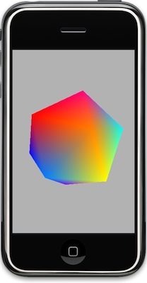
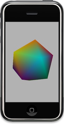
Now, if we run it, we do indeed get a rotating shape that looks like a real, gosh-honest-to-goodness three-dimensional object.
But what happened to our colors?
That, my friends, is our segue into the next installment of this series: OpenGL ES Materials. When you're using lighting and smooth shading, OpenGL expects you to provide materials (or textures, but we're not ready to segue there yet) for the polygons. Materials are more complex than the simple colors that we provided in the color array. Materials, like lights, are made of multiple components, and can be used to create a variety of different surface treatments. The actual appearance of objects is determined by the attributes of the scene's lights and the polygons' materials.
But, we don't want to leave off with a grey icosahedron, so in the meantime, I'll introduce you to another OpenGL ES configuration parameter that can be enabled: GL_COLOR_MATERIAL. By enabling this option like so:
glEnable(GL_COLOR_MATERIAL);
OpenGL will use the provided color array to create simple materials for our polygons based on the color array, giving a result more like this:
If you don't feel like typing everything in (or copying and pasting), you can check out the final project right here.