又一部前期JUSTECH(南京捷式泰)工程师职业发展系列丛书完整拷贝。
MPLS(Multi-Protocol Label Switching)
目录
1:MPLS 基础实验
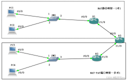
1.1实验拓扑

1.2实验需求:
a.要求取消PC1 PC2 设备路由功能,并且在PC1 PC2 按如下需求完成网关设置:
PC1 网关:172.16.1.1
PC2 网关:192.168.1.1
b.要求R2 R3 R4 启用EIGRP,AS 为1,R2 R4 将除172.16.1.0/24 及192.168.1.0/24网络都宣告进EIGRP
c.要求R2 R4 利用loopback 0 接口创建位于BGP 24 中的IBGP PEER 关系
d.要求R2 R4 将172.16.1.0/24 及192.168.1.0/24网络宣告进BGP进程
e.要求适当的设备参与MPLS 使得PC1 与PC2 能够相互通讯
1.3实验步骤
步骤1:完成基础配置
例如:接口的IP 地址,底层协议
此时管理员应该注意R2 与R4 是否通过BGP 学习到对方172及192路由,利用如下命令行查看:
R2#show ip bgp
BGP table version is 3, local router ID is 2.2.2.2
Status codes: s suppressed, d damped, h history, * valid, > best, i - internal,
r RIB-failure, S Stale
Origin codes: i - IGP, e - EGP, ? - incomplete
Network Next Hop Metric LocPrf Weight Path
*> 172.16.1.0/24 0.0.0.0 0 32768 i
*>i192.168.1.0 4.4.4.4 0 100 0 i
R2#show ip route bgp
B 192.168.1.0/24 [200/0] via 4.4.4.4, 00:00:55
R4#show ip bgp
BGP table version is 3, local router ID is 4.4.4.4
Status codes: s suppressed, d damped, h history, * valid, > best, i - internal,
r RIB-failure, S Stale
Origin codes: i - IGP, e - EGP, ? - incomplete
Network Next Hop Metric LocPrf Weight Path
*>i172.16.1.0/24 2.2.2.2 0 100 0 i
*> 192.168.1.0 0.0.0.0 0 32768 i
R4#show ip route bgp
172.16.0.0/24 is subnetted, 1 subnets
B 172.16.1.0 [200/0] via 2.2.2.2, 00:01:35
此时管理员是无法使得PC1 和PC2 通讯的,理由上R3 没有参与BGP 进程,所以当数据包丢给R3 时会出现丢包。
步骤2:配置MPLS
R2
Ip cef
Mpls label protocol ldp //设置标签分配分发协议为LDP
Mpls ldp router-id loopback 0 //设置当前LDP ROUTE-ID 为loopback 0 接口IP
Mpls label range 200 299 //设置当前LDP 标签分配时的取值范围
Interface e0/1
Mpls ip
R3
Ip cef
Mpls label protocol ldp //设置标签分配分发协议为LDP
Mpls ldp router-id loopback 0 //设置当前LDP ROUTE-ID 为loopback 0 接口IP
Mpls label range 300 399 //设置当前LDP 标签分配时的取值范围
Interface range e0/0 - 1
Mpls ip
R4
Ip cef
Mpls label protocol ldp //设置标签分配分发协议为LDP
Mpls ldp router-id loopback 0 //设置当前LDP ROUTE-ID 为loopback 0 接口IP
Mpls label range 400 499 //设置当前LDP 标签分配时的取值范围
Interface range e0/0
Mpls ip
假设管理员做完如上配置,应该看到控制台由如下信息提示管理员LDP 邻接关系建立完毕:
R3#
*Mar 1 00:23:46.699: %LDP-5-NBRCHG: LDP Neighbor 2.2.2.2:0 (1) is UP
R3#
*Mar 1 00:24:10.779: %LDP-5-NBRCHG: LDP Neighbor 4.4.4.4:0 (2) is UP
1.4校验
(1) 查看LDP 邻接关系发现
R3#show mpls ldp discovery //该命令行用于查看当前LSR是否通过LDP hello 消息发现LDP PEER
Local LDP Identifier: //本地LDP 的标示
3.3.3.3:0
Discovery Sources: //发现源:含义为什么接口接收了来自LDP PEER 的HELLO 消息,发现了PEER
Interfaces:
Ethernet0/0 (ldp): xmit/recv
LDP Id: 4.4.4.4:0; no host route //LDP peer 的标示,及标示的可达性信息
Ethernet0/1 (ldp): xmit/recv
LDP Id: 2.2.2.2:0; no host route
注意:
邻居发现时,LDP PEER ID 后面如果跟着上no host route ,是说当前LDP 设备没有抵达对端LDP ID 的主机路由。此时PEER 的ID 还是可达的。但是如果看到是no route ,那么基本意味着当前LDP 设备既没有抵达PEER ID 的网络路由也没有主机路由。
(2) 查看LDP 的邻接关系是否建立
R3#show mpls ldp neighbor //查看当前设备与LDP PEER 是否形成了LDP 邻接关系
Peer LDP Ident: 2.2.2.2:0; Local LDP Ident 3.3.3.3:0
TCP connection: 2.2.2.2.646 - 3.3.3.3.18578 //证明LDP 的TCP 连接已经建立
State: Oper; Msgs sent/rcvd: 19/20; Downstream //代表标签分发是基于下游主动(UD)
//state输出字段如果上oper那么是意味着邻接关系确认建立
Up time: 00:10:16
LDP discovery sources:
Ethernet0/1, Src IP addr: 31.31.23.2
Addresses bound to peer LDP Ident: //被限制地址
172.16.1.1 31.31.23.2 2.2.2.2
Peer LDP Ident: 4.4.4.4:0; Local LDP Ident 3.3.3.3:0
TCP connection: 4.4.4.4.12790 - 3.3.3.3.646
State: Oper; Msgs sent/rcvd: 19/20; Downstream
Up time: 00:09:52
LDP discovery sources:
Ethernet0/0, Src IP addr: 31.31.34.4
Addresses bound to peer LDP Ident:
31.31.34.4 192.168.1.1 4.4.4.4
(3) 查看MPLS 标签信息库(LIB)
R2#show mpls ldp binding
tib entry: 2.2.2.0/24, rev 2
local binding(本地标签): tag: imp-null(就是POP)
remote binding: tsr: 3.3.3.3:0, tag: 300
tib entry: 3.3.3.0/24, rev 4
local binding: tag: 200
remote binding: tsr: 3.3.3.3:0, tag: imp-null
tib entry: 4.4.4.0/24, rev 6
local binding: tag: 201
remote binding: tsr: 3.3.3.3:0, tag: 301
tib entry: 31.31.23.0/24, rev 10
local binding: tag: imp-null
remote binding: tsr: 3.3.3.3:0, tag: imp-null
tib entry: 31.31.34.0/24, rev 12
local binding: tag: 202
remote binding: tsr: 3.3.3.3:0, tag: imp-null
tib entry: 172.16.1.0/24, rev 8
local binding: tag: imp-null
R3#show mpls ldp bindings
tib entry: 2.2.2.0/24, rev 2
local binding: tag: 300
remote binding(LDP PEER 所分发过来的远程标签): tsr: 2.2.2.2:0(分发该标签的LDP PEER id), tag: imp-null(远端标签)
remote binding: tsr: 4.4.4.4:0, tag: 400
tib entry: 3.3.3.0/24, rev 4
local binding: tag: imp-null
remote binding: tsr: 2.2.2.2:0, tag: 200
remote binding: tsr: 4.4.4.4:0, tag: 401
tib entry: 4.4.4.0/24, rev 6
local binding: tag: 301
remote binding: tsr: 2.2.2.2:0, tag: 201
remote binding: tsr: 4.4.4.4:0, tag: imp-null
tib entry: 31.31.23.0/24, rev 8
local binding: tag: imp-null
remote binding: tsr: 2.2.2.2:0, tag: imp-null
remote binding: tsr: 4.4.4.4:0, tag: 402
tib entry: 31.31.34.0/24, rev 10
local binding: tag: imp-null
remote binding: tsr: 2.2.2.2:0, tag: 202
remote binding: tsr: 4.4.4.4:0, tag: imp-null
tib entry: 172.16.1.0/24, rev 11
remote binding: tsr: 2.2.2.2:0, tag: imp-null
tib entry: 192.168.1.0/24, rev 12
remote binding: tsr: 4.4.4.4:0, tag: imp-null
R4#show mpls ldp bindings
tib entry: 2.2.2.0/24, rev 2
local binding: tag: 400
remote binding: tsr: 3.3.3.3:0, tag: 300
tib entry: 3.3.3.0/24, rev 4
local binding: tag: 401
remote binding: tsr: 3.3.3.3:0, tag: imp-null
tib entry: 4.4.4.0/24, rev 6
local binding: tag: imp-null
remote binding: tsr: 3.3.3.3:0, tag: 301
tib entry: 31.31.23.0/24, rev 10
local binding: tag: 402
remote binding: tsr: 3.3.3.3:0, tag: imp-null
tib entry: 31.31.34.0/24, rev 12
local binding: tag: imp-null
remote binding: tsr: 3.3.3.3:0, tag: imp-null
tib entry: 192.168.1.0/24, rev 8
local binding: tag: imp-null
(4)查看MPLS的标签转发信息库(lfib)
R4#show mpls forwarding-table
Local Outgoing Prefix Bytes tag Outgoing Next Hop
tag tag or VC or Tunnel Id switched interface
400 300 2.2.2.0/24 0 Et0/0 31.31.34.3
401 Pop tag 3.3.3.0/24 0 Et0/0 31.31.34.3
402 Pop tag 31.31.23.0/24 0 Et0/0 31.31.34.3
local 字段:该字段表明特定网络的本地标签信息
Outgoing字段:该字段表明特定网络的关联的出站标签信息
prefix 字段:该字段表明目标网络
Bytes tagged switched 字段:表明有多少流量利用当前条目被转发
Outgoing interface 字段:表明本地出口
Next-hop 字段:表明下一跳
R3#show mpls forwarding-table
Local Outgoing Prefix Bytes tag Outgoing Next Hop
tag tag or VC or Tunnel Id switched interface
300 Pop tag 2.2.2.0/24 3502 Et0/1 31.31.23.2
301 Pop tag 4.4.4.0/24 2422 Et0/0 31.31.34.4
R2#show mpls forwarding-table
Local Outgoing Prefix Bytes tag Outgoing Next Hop
tag tag or VC or Tunnel Id switched interface
200 Pop tag 3.3.3.0/24 0 Et0/1 31.31.23.3
201 301 4.4.4.0/24 0 Et0/1 31.31.23.3
202 Pop tag 31.31.34.0/24 0 Et0/1 31.31.23.3
(2) PC2 为源PING 172.16.1.2
PC2#ping 172.16.1.2
Type escape sequence to abort.
Sending 5, 100-byte ICMP Echos to 172.16.1.2, timeout is 2 seconds:
!!!!!
1.5 思考题
(1)MPLS LDP 邻接关系发现利用的是什么消息,什么方法?
(2)mpls ldp 邻接关系的建立用的是TCP 还是UDP,如何建立?
(3)请描述标签分配、分发、关联过程?
(4)请描述POP tag untag的作用?
(5)请描述被限制地址的作用?
(6)请描述在该拓扑中数据传递的整个过程?
2:MPLS 转发地址实验
2.1 实验拓扑
2.2 实验需求
a.要求管理员根据拓扑图需求完成R1 R2的接口配置,这里不允许启用任何动态路由协议或静态路由。
b.要求R1 与 R2 将本地的loopback 0配置为ldp 的ROUTER-ID,最终形成R1 与R2 间的LDP邻接关系。
2.3 实验步骤
步骤1:完成基础配置
例如:接口IP地址
步骤2:完成R1 与R2上的MPLS 配置
R1 R2
Ip cef
Mpls label protocol ldp
Mpls label range x y
Mpls ldp router-id loopback 0
Int e0/0
Mpls ip
此时管理员可以再R1 或R2 上利用如下命令来观察MPLS LDP 的邻接发现信息,现象如下:
R1#show mpls ldp discovery detail
Local LDP Identifier:
1.1.1.1:0
Discovery Sources:
Interfaces:
Ethernet0/0 (ldp): xmit/recv
Enabled: Interface config
Hello interval: 5000 ms; Transport IP addr: 1.1.1.1
//这里的transport ip address 可以说明确实默认情况下LDP 的传输地址就是LDP 的ROUTER-ID
LDP Id: 2.2.2.2:0; no route to transport addr
//该部分显示当前设备根本没有抵达对等体传输地址的路由路径信息
Src IP addr: 31.31.12.2; Transport IP addr: 2.2.2.2
Hold time: 15 sec; Proposed local/peer: 15/15 sec
R2#show mpls ldp discovery detail
Local LDP Identifier:
2.2.2.2:0
Discovery Sources:
Interfaces:
Ethernet0/0 (ldp): xmit/recv
Enabled: Interface config
Hello interval: 5000 ms; Transport IP addr: 2.2.2.2
LDP Id: 1.1.1.1:0; no route to transport addr
Src IP addr: 31.31.12.1; Transport IP addr: 1.1.1.1
Hold time: 15 sec; Proposed local/peer: 15/15 sec
步骤3:在接口下修改当前LDP 进程的传输地址信息
R1
Interface e0/0
mpls ldp discovery transport-address 31.31.12.1
//该命令行用于修改当前LDP 进程所发送的消息的源地址,当然也是修改传输地址
R2
Interface e0/0
mpls ldp discovery transport-address 31.31.12.2
此时管理员应该再次通过 “show mpls ldp discovery detail”来查看传输地址是否变化,现象如下:
R1#show mpls ldp discovery detail
Local LDP Identifier:
1.1.1.1:0
Discovery Sources:
Interfaces:
Ethernet0/0 (ldp): xmit/recv
Enabled: Interface config
Hello interval: 5000 ms; Transport IP addr: 31.31.12.1
LDP Id: 2.2.2.2:0; no host route to transport addr
Src IP addr: 31.31.12.2; Transport IP addr: 31.31.12.2
Hold time: 15 sec; Proposed local/peer: 15/15 sec
Reachable via 31.31.12.0/24
R2#show mpls ldp discovery detail
Local LDP Identifier:
2.2.2.2:0
Discovery Sources:
Interfaces:
Ethernet0/0 (ldp): xmit/recv
Enabled: Interface config
Hello interval: 5000 ms; Transport IP addr: 31.31.12.2
LDP Id: 1.1.1.1:0; no host route to transport addr
Src IP addr: 31.31.12.1; Transport IP addr: 31.31.12.1
Hold time: 15 sec; Proposed local/peer: 15/15 sec
Reachable via 31.31.12.0/24
2.4 校验
(1)确认R1 与R2 建立了LDP 邻接关系
2.5 思考题
(1)请解释传输地址的意义?
3:MPLS MTU 实验
3.1 配置方法:
Interface
Mpls mtu <1504/1508/1512>
实验1要求将R2 的FA 0/0 及FA 0/1 接口MPLS MTU 改为100,并观察现象。
4:MPLS TTL 实验
4.1 实验拓扑
4.2 实验需求
a. 按拓扑要求完成基础配置
b. 在开启和关闭TTL 传播功能的环境下查看traceroute 命令的输出画面
4.3 配置步骤
步骤1:完成基础配置
例如:接口IP
R2 R1 间OSPF ,R5 R6 间OSPF
底层协议EIGRP 和BGP的配置
router bgp 25
bgp redistribute-internal // 允许IBGP PEER 路由重分发进IGPS 协议
MPLS 配置
步骤2:在路由器运行MPLS 默认开启TTL 传播功能的情况下,在R1上利用如下命令探测路径:
R1#traceroute
Protocol [ip]:
Target IP address: 31.31.56.6 //指定被探测路径的目标IP
Source address: 31.31.12.1 //指定被探测路径的源IP
Numeric display [n]:
Timeout in seconds [3]:
Probe count [3]:
Minimum Time to Live [1]:
Maximum Time to Live [30]:
Port Number [33434]:
Loose, Strict, Record, Timestamp, Verbose[none]:
Type escape sequence to abort.
Tracing the route to 31.31.56.6
1 31.31.12.2 40 msec 60 msec 28 msec
2 31.31.23.3 192 msec 156 msec 204 msec
3 31.31.34.4 232 msec 248 msec 152 msec
4 31.31.45.5 244 msec 264 msec 156 msec
5 31.31.56.6 280 msec * 312 msec
此时管理员通过如上信息可以发现,实际上数据包经过的每台设备的下一跳都被显示。
步骤3:在R2 上关闭TTL-传播功能
R2
no mpls ip propagate-ttl forwarded
步骤4:在关闭TTL-传播功能的情况下,在R1上做路径探测
R1#traceroute
Protocol [ip]:
Target IP address: 31.31.56.6
Source address: 31.31.12.1
Numeric display [n]:
Timeout in seconds [3]:
Probe count [3]:
Minimum Time to Live [1]:
Maximum Time to Live [30]:
Port Number [33434]:
Loose, Strict, Record, Timestamp, Verbose[none]:
Type escape sequence to abort.
Tracing the route to 31.31.56.6
1 31.31.12.2 48 msec 92 msec 32 msec
2 31.31.45.5 232 msec 188 msec 156 msec
3 31.31.56.6 236 msec * 188 msec
那么此时如上现象告诉我们只有接收IP包的路由器被路径探测发现,而那些运行MPLS 的路由器却都被隐藏。
5:MPLS 出方向标签通告过滤实验
5.1 实验拓扑
5.2 实验需求
a. R1 R2 R3 启用EIGRP 当做底层路由协议
b.R1 R2 R3 将所有loopback 接口及物理接口网络宣告进EIGRP
c.R1 R2 R3 参与MPLS,用LDP 当做标签分配、分发协议
d.要求R2 不将1.1.1.0/24网络的本地标签信息发送给R3
5.3 实验步骤
步骤1:完成基础配置
例如:接口IP底层协议
完成如上配置管理员需要确认R1 R2 R3 形成了EIGRP 邻接关系,并且学习了对方loopback 接口网络。
步骤2:完成MPLS 配置
R1
No mpls ldp advertise-label //关闭R1标签通告功能
Ip cef
Mpls label protocol ldp
Mpls label range 100 199
Mpls ldp router-id lo 0
Int e0/0
Mpls ip
R2
No mpls ldp advertise-label //关闭R2标签通告功能
Ip cef
Mpls label protocol ldp
Mpls label range 200 299
Mpls ldp router-id lo 0
Int e0/0 -1
Mpls ip
R3
No mpls ldp advertise-label
Ip cef
Mpls label protocol ldp
Mpls label range 300 399
Mpls ldp router-id lo 0
Int e0/1
Mpls ip
此时由于标签通告功能被关闭,我们查看R1 R2 R3 的LIB(标签信息库)应该只能看到当前LSR对本地网络分配的本地标签,而看不到任何LSR 对等体发送过来的远程标签信息,现象如下:
R1#show mpls ldp bindings
tib entry: 1.1.1.0/24, rev 2
local binding: tag: imp-null
tib entry: 2.2.2.0/24, rev 4
local binding: tag: 100
tib entry: 3.3.3.0/24, rev 6
local binding: tag: 101
tib entry: 31.31.12.0/24, rev 8
local binding: tag: imp-null
tib entry: 31.31.23.0/24, rev 10
local binding: tag: 102
R2#show mpls ldp bindings
tib entry: 1.1.1.0/24, rev 2
local binding: tag: 200
tib entry: 2.2.2.0/24, rev 4
local binding: tag: imp-null
tib entry: 3.3.3.0/24, rev 6
local binding: tag: 201
tib entry: 31.31.12.0/24, rev 8
local binding: tag: imp-null
tib entry: 31.31.23.0/24, rev 10
local binding: tag: imp-null
R3#show mpls ldp bindings
tib entry: 1.1.1.0/24, rev 2
local binding: tag: 300
tib entry: 2.2.2.0/24, rev 4
local binding: tag: 301
tib entry: 3.3.3.0/24, rev 6
local binding: tag: imp-null
tib entry: 31.31.12.0/24, rev 8
local binding: tag: 302
tib entry: 31.31.23.0/24, rev 10
local binding: tag: imp-null
步骤3:在R2 上针对R3 这个LDP 对等体,过滤掉1.1.1.0/24网络的标签公告信息
R1 R3
Mpls ldp advertise-label //开启MPLS 标签通告功能
R2
Access-list 1 permit 31.31.12.0 0.0.0.255 //利用该ACL 方形被允许当做标签通告内容的网络
Ip access-list standard ACL2
Permit 3.3.3.3 0.0.0.0 //用该ACL匹配远端LDP 邻居的传输地址
Mpls ldp advertise-label for 1 to ACL2
5.4 校验
(1) 此时我们在R3上利用”show mpls ldp binding”命令,应该看到如下输出画面:
R3#show mpls ldp bindings
tib entry: 1.1.1.0/24, rev 11
local binding: tag: 300
tib entry: 2.2.2.0/24, rev 12
local binding: tag: 301
tib entry: 3.3.3.0/24, rev 13
local binding: tag: imp-null
tib entry: 31.31.12.0/24, rev 14
local binding: tag: 302
remote binding: tsr: 2.2.2.2:0, tag: imp-null
tib entry: 31.31.23.0/24, rev 15
local binding: tag: imp-null
6:MPLS 入方向标签通告过滤
6.1 实验拓扑
6.2 实验需求
a. R1 R2 R3 启用EIGRP 当做底层路由协议
b.R1 R2 R3 将所有loopback 接口及物理接口网络宣告进EIGRP
c.R1 R2 R3 参与MPLS,用LDP 当做标签分配、分发协议
d.要求R3 不希望接收到1.1.1.0 的远程标签
6.3 配置步骤
步骤1:完成基础配置
例如:IP地址
底层协议
MPLS 配置(注意关闭R2的标签通告功能)
步骤2:在R3 上完成入方向标签通告过滤配置,并且开启R2的标签通告功能:
R2
Mpls ldp advertise-label
R3
Access-list 1 permit 31.31.12.0 0.0.0.255
access-list 1 permit 2.2.2.0 0.0.0.255
Mpls ldp neighbor 2.2.2.2 labels accept 1
6.4 校验
(1) 在R3 上利用”show mpls ldp binding”查看是否只学习了31.31.12.0对应的远程标签,现象如下:
R3#show mpls ldp bindings
tib entry: 1.1.1.0/24, rev 11
local binding: tag: 300
tib entry: 2.2.2.0/24, rev 12
local binding: tag: 301
tib entry: 3.3.3.0/24, rev 13
local binding: tag: imp-null
tib entry: 31.31.12.0/24, rev 14
local binding: tag: 302
remote binding: tsr: 2.2.2.2:0, tag: imp-null
tib entry: 31.31.23.0/24, rev 15
local binding: tag: imp-null
7:MPLS 的LDP 认证实验
7.1 实验拓扑
7.2 实验需求
a.所有接口参与EIGRP AS 1
b.要求R1 R2 形成LDP 邻接关系,并且启用LDP 认证,密码为PASSCCIE
7.3 实验步骤
步骤1:完成基础配置
例如:所有接口配置IP
所有网络宣告进EIGRP
步骤2:完成R1 R2 上的MD5密文认证
R1
Mpls ldp neighbor 2.2.2.2 password justech
R2
Mpls ldp neighbor 1.1.1.1 password justech
7.4 校验
(1) 确认LDP 的邻接关系建立